Power-assisted bicycle with magnetic flux sensor with multiple magnet blocks nonuniformly arranged on flywheel

A magnetic flux sensor, a technology for assisting bicycles, which is applied in the direction of transmission of sensing components, vehicle components, and rider driving by means of electric/magnetic devices, which can solve the problems of unstable operation of motors, no control signals, and different problems.

Active Publication Date: 2014-02-05
徐州凯迪桑拿设备有限公司
View PDF12 Cites 0 Cited by
  • Summary
  • Abstract
  • Description
  • Claims
  • Application Information

AI Technical Summary

Problems solved by technology

[0015] Disadvantages (1) Using two permanent magnetic steels with no difference to represent the fixed positions of the two pedals, only multiple Halls can be used to represent the rotational positions of the pedals: the two magnetic steels have no difference, and the advantages are The fixed position of the two pedals can be indicated regardless of the left and right feet, so that the left and right feet can generate power assistance requirements, which can produce the same motor power assistance effect; but the disadvantage is that the permanent magnet itself cannot indicate the rotational position of the pedals, but can only Use multiple Halls at different corner positions to indicate the rotational position of the pedal, so you cannot use only one Hall, but must use multiple Halls
[0016] Disadvantage (2) Only one Hall cannot be used, but three Halls will inevitably cause the original segmentation error of the three control signals, which will distort the power-assist demand model, naturally The generation of power output is inconsistent with the demand for power assistance: no matter whether the power-assisted bicycle has one or two motors, the sensor signal for controlling the motor can only be controlled by using one sensor signal input to the motor controller; and the patent uses three sensors. If Hall controls the motor, the three control signals of the three Halls must be combined into one combined control signal before it can be input to the motor controller
The sensing parameters of the three Halls cannot be the same, especially due to changes in ambient temperature and long-term use, the sensing parameters of the three Halls may vary greatly. The output voltages are different, resulting in different power output of the motor, and the power output is inconsistent with the power demand; similarly, when the power demand is the same, the outputs of different Halls may be the same voltage, resulting in the same power output of the motor, and also There is a problem that the power output is inconsistent with the power demand
[0017] Disadvantages (3) The combined control signal is prone to signal drift, which makes the combined control signal not match the motor controller, and the power-assisted demand model is distorted: due to changes in ambient temperature and use time After a long period of time, the sensing parameters of the three Halls may vary greatly, and the connection points of the three control signals of the three Halls will inevitably change, so the combined control signals generated by the same boosting demand will produce segmental signal drift. Combining the control signals as a whole produces signal distortion, that is, the power-assist demand model is distorted, causing the motor controller to choose any one of the three control signals as a reference, resulting in the inconsistency between the power-assisted output and the power-assisted demand
[0018] Disadvantage (4) The sensing points cannot be increased arbitrarily. If there are too few sensing points, the motor will not run smoothly, making the rider feel very uncomfortable: due to the disadvantages (1) and (2) are the most important The number of halls is greater than one. Obviously, the more the number of halls, the more serious the shortcomings (1) and (2) are.
Therefore, the power-assisted bicycle provided by this patent can only be a very bad power-assisted bicycle that makes the rider feel comfortable.
[0019] Disadvantages (5) The signal blind area reaches 42 degrees, and when the power is needed when starting, it is impossible to get it: as we all know, the torque of the bicycle pedal is the smallest at the apex , from the angle of 10-45 degrees away from the top is the area that needs the most assistance, but the angle between the Halls in this patent is 42.5-43.5 degrees, and there is no Hall in the area of ​​10-42 degrees away from the top of the pedal. There is no control signal, and the result is when the assist is most needed, but the motor of the assist bicycle cannot assist
[0020] In short, this patent is a technical solution for using multiple Halls to control the booster mode, because only multiple Halls can be used to represent the rotation position of the pedal, and the multiple control signals of multiple Halls must have original errors, and the combined control signals It is also easy to produce signal drift, which can cause distortion of the assist demand model, that is, the same assist demand at different times, but different assist effects; the more the number of Halls, the more serious the distortion of the assist demand model, limiting the number of Halls , a small amount of Hall will cause the motor to run unsteadily, making the rider feel very uncomfortable, and will not get assistance when starting
To make it undistorted to help the demand model, and to ensure the smooth operation of the motor, there are always two issues. It is impossible to have both.

Method used


Image

  • Power-assisted bicycle with magnetic flux sensor with multiple magnet blocks nonuniformly arranged on flywheel
  • Power-assisted bicycle with magnetic flux sensor with multiple magnet blocks nonuniformly arranged on flywheel
  • Power-assisted bicycle with magnetic flux sensor with multiple magnet blocks nonuniformly arranged on flywheel

Examples


Embodiment 1

[0114] Embodiment 1. A power-assisted bicycle with multi-magnetic blocks and unevenly distributed magnetic flux sensors on the flywheel

[0115] Such as figure 1 , 3 , 4, 6,

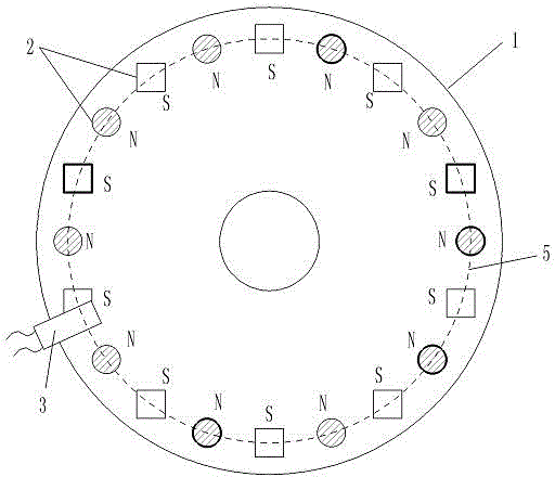
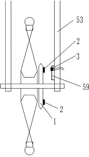
[0116] 1. The components and structure of the electric bicycle related to the installation of the sensor: including the electric bicycle and the sensor, the rear wheel of the electric bicycle has a flywheel 1, the electric bicycle has a frame 53, the battery 55 on the electric bicycle is connected to the motor controller 29, and the motor controller 29 connect the motor 30 on the wheel.

[0117] 2. The structure of the sensor and the connection relationship of the components are as follows:

[0118] The sensor includes a sensing element connected in sequence, a boost model processor 21, a digital-to-analog converter 27 and an operational amplifier 28;

[0119] [1] The sensing element is an element that converts the rotational motion of the flywheel 1 into a rectangular wave signal output;

[0120] ...

Embodiment 2

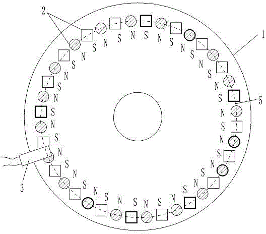
[0136] Embodiment 2. A power-assisted bicycle with multi-magnet unevenly distributed magnetic flux sensors on a high-density flywheel

[0137] Such as figure 2 , 3 , 4, 6, 40 permanent magnet blocks 2 with a diameter of 0.6 cm are arranged on one surface of a flywheel 1 with a diameter of 10.0 cm. The magnetic flux of the permanent magnet block 2 is 146---279 (B·H)max / KJ·m -3 Different selection values ​​within the range, and the magnetic flux of the adjacent permanent magnet block 2 is not equal, Hall 3 keeps a distance of 0.2 cm from each permanent magnet block 2 in the rotating state, so that each permanent magnet block 2 that is rotating Hall 3, Hall 3 can generate a corresponding rectangular wave signal output. Other structures are the same as in Embodiment 1.

Embodiment 3

[0138] Embodiment 3, a power-assisted bicycle with multi-magnetic blocks unevenly distributed magnetic flux sensors on a flywheel with a specific circuit

[0139] Such as figure 1 , 3 , 5, 6, as in embodiment 1, the sensor includes a sensing element connected in sequence, a booster model processor 21, a digital-to-analog converter 27 and an operational amplifier 28;

[0140] [1] The Hall 3 in the sensing element is UGN3075; the structure of other elements and elements in the sensing element is the same as that in Embodiment 1;

[0141] [2] The auxiliary model processor 21 selects the single-chip microcomputer 31 to complete all functions, and the single-chip microcomputer 31 selects AT89S52. That is, the AT89S52 single-chip microcomputer 31 completes all functions of the analog-to-digital conversion and the peak recognizer 22, the power-assisted starting point selector 23, the magnetic block rotational speed calculator 24, the power-assisted model memory 25 and the power-as...


PUM


Abstract

The invention discloses an assisted bicycle with a magnetic flux sensor with a plurality of magnet blocks nonuniformly arranged on a flywheel, and belongs to an electric assisted bicycle which can provide assistance signals by multi-point magnetic induction. The sensor comprises a sensing element, an assistance model processor, a digital-to-analogue converter and an operational amplifier which are connected in sequence, wherein a plurality of permanent magnet blocks are fixedly arranged on the flywheel serving as the sensing element, and the magnetic polarities of adjacent permanent magnet blocks are opposite to each other; magnetic fluxes of the permanent magnet blocks are different from each other; a Hall element of the sensing element is arranged on a bicycle frame close to the permanent magnet blocks; and the operational amplifier is connected with a motor controller. The assisted bicycle has the advantages that the Hall element can acquire square-wave signals, and the square-wave signals are subjected to the digital processing by the sensor and an assistance model is set artificially; the start point, the end point, and the power of the assistance are reasonable; and man and machine can be matched and electricity can be saved.

Description

technical field [0001] The invention belongs to the technical field of power-assisted bicycles, in particular to an electric power-assisted bicycle that performs multi-point magnetic induction on a rotating part to provide power-assisted signals. Background technique [0002] The Chinese patent 201020295192.0 "Claw Type Torque Sensing Device" applied by Yebao Vehicle Material Industry (Kunshan) Co., Ltd. discloses a sensing device for power-assisted bicycles. The sensing device includes a magnetic part and an elastic part to sense the torque. sensing device. After a long time of use, the change of the elastic coefficient of the elastic member will lead to changes in the sensing signal and the control effect of the controlled motor, and the power-assisted effect will not match the power-assisted needs of people. Moreover, the design structure of the elastic member is complex and the manufacturing cost is high. [0003] The Chinese patent 01201843.0 "Automatic Detection Devi...

Claims


Application Information

Patent Timeline
Patent Type & Authority Patents(China)
IPC IPC(8): B62M6/50G01D5/244
Inventor 高冠宇黄强
Owner 徐州凯迪桑拿设备有限公司
Why Eureka
Try Eureka