Bistable state photonic crystal

A photonic crystal and bistable technology, applied in optics, nonlinear optics, instruments, etc.

Inactive Publication Date: 2013-01-02
叶哲良
View PDF4 Cites 0 Cited by
  • Summary
  • Abstract
  • Description
  • Claims
  • Application Information

AI Technical Summary

Problems solved by technology

Therefore, there has never been a variable photonic crystal that can simultaneously have a wide wavelength modulation range and a fast response time in the prior art.

Method used


Image

  • Bistable state photonic crystal
  • Bistable state photonic crystal
  • Bistable state photonic crystal

Examples


Embodiment Construction

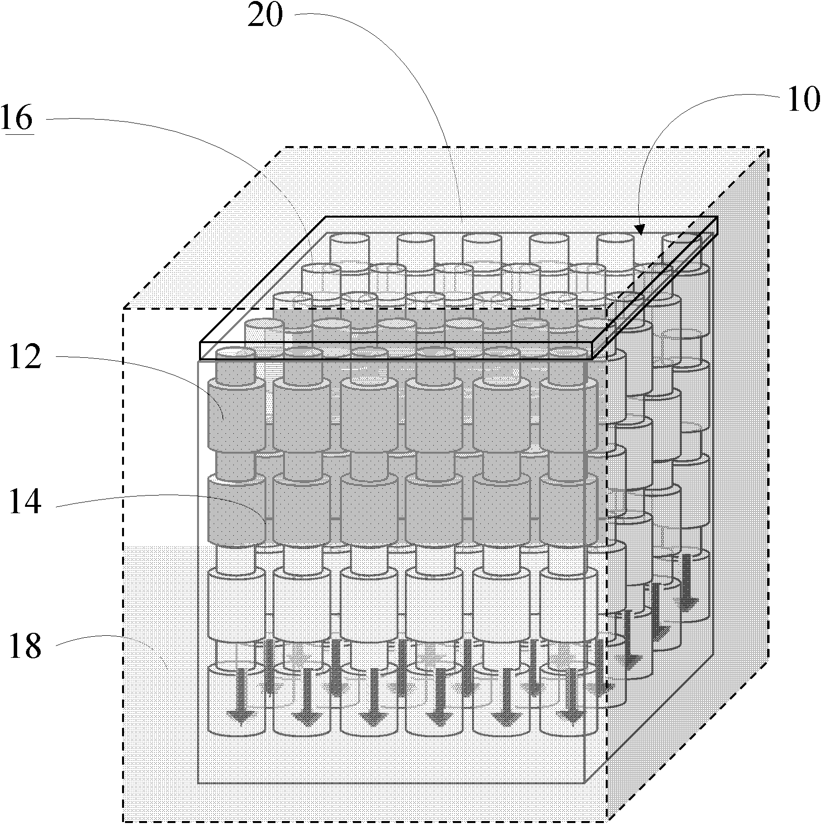
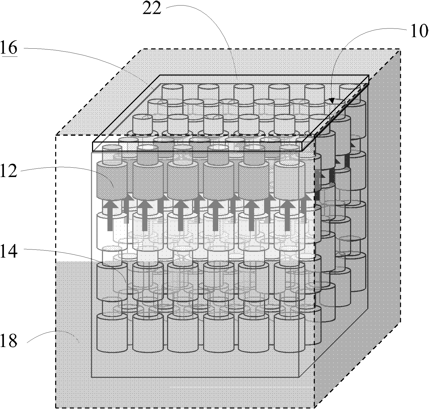
[0019] see figure 1 and figure 2 . figure 1 It is a schematic diagram showing the photonic crystal coated with the first liquid of the present invention, figure 2 It is a schematic diagram illustrating the coating of the second liquid on the photonic crystal of the present invention. The present invention provides a bistable photonic crystal 10, which has a plurality of holes 12, and each hole 12 has a hydrophobic layer 14 on its surface. When the photonic crystal 10 is immersed in a predetermined liquid 18, the photonic crystal 10 has a first steady state and a second steady state, wherein the first steady state makes the predetermined liquid 18 fill the plurality of holes 12 of the photonic crystal 10, and the second steady state The steady state excludes the predetermined liquid 18 from the plurality of holes 12 of the photonic crystal 10 .

[0020] According to a specific embodiment, the photonic crystal 10 of the present invention has a surface 16, and the first sta...


PUM


Abstract

The invention discloses a bistable state photonic crystal which is provided with a plurality of holes. A dewatering layer is arranged on the surface of each hole, and when the photonic crystal is immersed in scheduled liquid, the photonic crystal is provided with a first steady state and a second steady state, the first steady state enables the scheduled liquid to be filled in the plurality of holes of the photonic crystal, and the second steady state enables the scheduled liquid to be discharged out of the plurality of holes of the photonic crystal. The bistable state photonic crystal can maintain at any steady state on the premise of needing no external energy due to energy barrier between the first steady state and the second steady state.

Description

technical field [0001] The present invention relates to a bistable photonic crystal, in particular to a photonic crystal capable of maintaining one of two stable states without external energy consumption. Background technique [0002] Photonic crystals are nanostructures with a periodic refractive index, which can change the transmission of light. It is the latest technology that the industry is looking forward to being widely used in future optical communications, displays and optical calculators. At present, the development of photonic crystal technology mainly lies in its manufacturing and driving modulation methods. The traditional photonic crystal color-changing technology mainly uses electrochemical methods, and the refractive index of the material is changed by the expansion of chemical solvents, thus producing color changes. However, the control technology of conventional photonic crystals is limited by the liquid diffusion speed (~10-3m / s) and material limitations,...

Claims


Application Information

Patent Timeline
Patent Type & Authority Applications(China)
IPC IPC(8): G02F1/01
Inventor 叶哲良詹佳璁
Owner 叶哲良
Why Eureka
Try Eureka