High-pulse-contrast-ratio nanosecond fiber laser

A fiber laser and contrast technology, applied in the laser field, can solve the problems of easy aging at the connection between the coupling fiber and the crystal, low output power of the semiconductor seed source, and deterioration of the pulse contrast, etc. The effect of low insertion loss

Inactive Publication Date: 2013-06-19
广东华快光子科技有限公司
View PDF7 Cites 2 Cited by
  • Summary
  • Abstract
  • Description
  • Claims
  • Application Information

AI Technical Summary

Problems solved by technology

The existing Q-switch actually adds fiber coupling to the bulk acousto-optic crystal, and is not strictly an all-fiber device. Under long-term working conditions, the connection between the coupling fiber and the crystal is prone to aging, and the long-term stability of the acousto-optic Q-switch still needs to be improved.
[0004] The nanosecond pulsed laser with MOPA structure has the advantages of tunable pulse width and repetition frequency, controllable pulse shape, and a large adjustable range of parameters. However, due to the small output power of the semiconductor seed source, it is generally necessary to use a cascaded structure of multiple amplifiers. High cost and relatively complicated system
In the multi-stage amplification process, it is easy to generate amplified spontaneous radiation noise, causing a DC light background, degrading the pulse contrast, and causing pulse deformation
At the same time, some length-related nonlinear effects in optical fibers, such as stimulated Raman scattering, also increase with the increase of optical fiber links, and even burn out the optical fiber in severe cases

Method used


Image

  • High-pulse-contrast-ratio nanosecond fiber laser
  • High-pulse-contrast-ratio nanosecond fiber laser
  • High-pulse-contrast-ratio nanosecond fiber laser

Examples


Embodiment 1

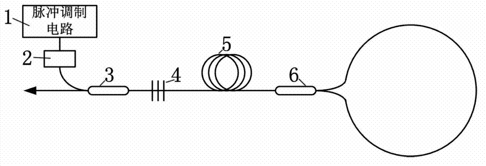
[0027] Such as figure 1 As shown, a nanosecond fiber laser with high pulse contrast includes a pulse modulation circuit 1 , a pump laser 2 , a beam combiner 3 , a fiber grating 4 , a gain fiber 5 and a fiber loop mirror 6 .

[0028] The pump laser 2 is a semiconductor laser, and its central wavelength corresponds to the absorption line of the gain fiber 5 .

[0029] The beam combiner 3 is a wavelength division multiplexer or a high power beam combiner.

[0030] The gain fiber 5 is a single-mode or double-clad gain fiber doped with rare earth element ions.

[0031] The fiber loop mirror 6 includes a directional fiber coupler and a fiber loop loop formed by connecting two output ports of the coupler. The coupler is a tapered all-fiber device with an arbitrary splitting ratio.

[0032] The lasers propagating clockwise and counterclockwise along the fiber loop in the fiber loop mirror 6 interfere with each other at the output port, changing the beam splitting ratio of the direct...

Embodiment 2

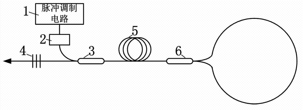
[0035] Such as figure 2 As shown, a nanosecond fiber laser with high pulse contrast includes a pulse modulation circuit 1 , a pump laser 2 , a beam combiner 3 , a fiber grating 4 , a gain fiber 5 and a fiber loop mirror 6 .

[0036] The pump laser 2 is a semiconductor laser, and the central wavelength corresponds to the absorption line of the gain medium of the gain fiber 5 .

[0037] The beam combiner 3 is a wavelength division multiplexer or a high power beam combiner.

[0038] The gain fiber 5 is a single-mode or double-clad gain fiber doped with rare earth element ions.

[0039] The fiber loop mirror 6 includes a directional fiber coupler and a fiber loop loop formed by connecting two output ports of the coupler. The coupler is a tapered all-fiber device with an arbitrary splitting ratio.

[0040] Driven by the pulse modulation circuit 1, the pumping semi-laser 2 generates pumping light with a time-domain width on the order of microseconds and a central wavelength corre...

Embodiment 3

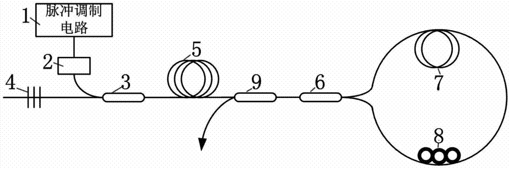
[0042] Such as image 3As shown, a nanosecond fiber laser with high pulse contrast includes a pulse modulation circuit 1, a pump laser 2, a beam combiner 3, a fiber grating 4, a gain fiber 5, a fiber loop mirror 6, an optical fiber 7, and a polarization controller 8, fiber optic coupler 9.

[0043] The pump laser 2 is a semiconductor laser, and the central wavelength corresponds to the absorption line of the gain medium of the gain fiber 5 .

[0044] The beam combiner 3 is a wavelength division multiplexer or a high power beam combiner.

[0045] The gain fiber 5 is a single-mode or double-clad gain fiber doped with rare earth element ions.

[0046] Described optical fiber loop mirror 6 comprises a directional fiber coupler and a fiber circle loop part formed by connecting together two output ports of the coupler, the coupler is a tapered all-fiber device with arbitrary splitting ratio, optical fiber 7 and polarization The controller 8 is arranged in the loop part of the fib...


PUM


Abstract

The invention discloses a high-pulse-contrast-ratio nanosecond fiber laser which comprises a pump laser, a pump combiner, a gain fiber, a fiber loop mirror and a fiber bragg grating. Lasers which are propagated along a fiber ring, in the clockwise direction and the counter clockwise direction, in the fiber loop mirror, are mutually intervened at the output port, the splitting ratio of the coupler is changed, power size of transmission light and reflected light can be changed, and the fiber loop mirror and the fiber bragg grating collectively form a resonant cavity. The high-pulse-contrast-ratio nanosecond fiber laser has the advantages of being compact in structure, good in stability, high in switching speed, and high in pulse contrast ratio. In addition, light leakage cannot occur when the high-pulse-contrast-ratio nanosecond fiber laser is used for marking and engraving and the like of sensitive materials, machining edges are clear, and effects are better.

Description

[technical field] [0001] The invention relates to a nanosecond fiber laser with high pulse contrast and belongs to the field of laser technology. [Background technique] [0002] Nanosecond laser pulses with single pulse energy on the order of millijoules are widely used in the fields of electronics, clothing, and chip manufacturing, especially in sensitive golden plastic paint stripping, stainless steel coloring, and flexible ceramic drilling. The demand for fiber laser is particularly urgent. There are two main types of nanosecond pulse lasers commonly used in the field of industrial processing: acousto-optic Q-switched nanosecond pulse lasers and MOPA structure pulse lasers with seed source oscillation and main amplification. [0003] Acousto-optic Q-switched nanosecond pulsed laser technology is mature and has a high market share, but it is limited by the transmittance and response speed of the Q switch, the pulse time domain is asymmetrical, and the falling edge has hun...

Claims


Application Information

Patent Timeline
Patent Type & Authority Applications(China)
IPC IPC(8): H01S3/067H01S3/08
Inventor 梁崇智曾和平杨康文
Owner 广东华快光子科技有限公司
Why Eureka
Try Eureka