Grin-lensed, tuned wedge waveguide termination and method of reducing back reflection caused thereby

a wedge waveguide and wedge waveguide technology, applied in the direction of lamination ancillary operations, instruments, chemistry apparatus and processes, etc., can solve the problems of high loss, inability to withstand extreme temperatures, chemicals or abrasion, and many of the ar coatings b>102/b> to be cured, etc., to achieve low insertion loss

Active Publication Date: 2013-02-14
LAUGHLIN GREG S
View PDF5 Cites 68 Cited by
  • Summary
  • Abstract
  • Description
  • Claims
  • Application Information

AI Technical Summary

Benefits of technology

[0008]Many specifications today, such as MIL-DTL-38999, specify a maximum of −35 dB back reflection. As the ability to measure back reflection has increased to −50 dB and perhaps beyond, demand is building for waveguide terminations having less than a −50 dB back reflection, while exhibiting a relatively low insertion loss.

Problems solved by technology

These Fresnel back reflections are typically −10 dB to −15 dB, which have become unacceptable.
Unfortunately, many of these AR coatings 102 cannot withstand exposure to extreme temperatures, chemicals or abrasion.
Also disadvantageous is the fact that while the back reflections have been rerouted, the losses they represent remain.

Method used


Image

  • Grin-lensed, tuned wedge waveguide termination and method of reducing back reflection caused thereby
  • Grin-lensed, tuned wedge waveguide termination and method of reducing back reflection caused thereby
  • Grin-lensed, tuned wedge waveguide termination and method of reducing back reflection caused thereby

Examples


Embodiment Construction

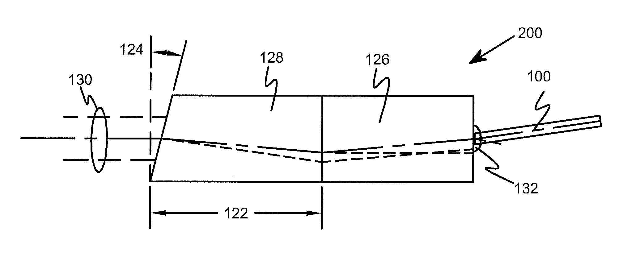
[0026]It is realized herein that a quarter-pitch GRIN lens produces a primary beam that is fully spread as it exits the quarter-pitch GRIN lens. It is further realized herein that, because the primary beam is fully spread, a substantial fraction of its total energy cannot be captured and is therefore lost. It is realized herein that their reliance on of quarter-pitch GRIN lenses is, at least in part, why the conventional orthogonal and beveled GRIN-lensed collimators described in the Background above exhibit significant insertion losses. It is also realized herein that the acute disadvantages of quarter-pitch GRIN lenses in this regard apparently have not been appreciated in the prior art, because quarter-pitch GRIN lenses have many positive qualities in other applications and are therefore widely accepted and employed.

[0027]Consequently, it is still further realized herein that a GRIN lens having a greater-than-quarter-pitch would advantageously produce a primary beam that is conve...


PUM

PropertyMeasurementUnit
angleaaaaaaaaaa
insertion lossaaaaaaaaaa
lengthaaaaaaaaaa

Abstract

A GRIN-lensed, tuned wedge waveguide termination, a method of reducing back reflection to a waveguide caused by the GRIN-lensed, tuned wedge waveguide termination and a terminated optical fiber. In one embodiment, the GRIN-lensed, tuned wedge waveguide termination includes: (1) a GRIN lens subassembly including a GRIN lens having a pitch greater than a quarter pitch such that a primary beam propagating through the GRIN lens subassembly forms a waist and (2) a tuned wedge subassembly bonded to the GRIN lens subassembly and having a length selected such that the tuned wedge subassembly ends at least proximate the waist, the tuned wedge subassembly further having a bevel angle selected to reduce a back reflection into the waveguide.

Description

CROSS-REFERENCE TO RELATED APPLICATION[0001]This application claims the benefit of U.S. Provisional Application Ser. No. 61 / 521,222, filed by Laughlin on Aug. 8, 2011, entitled “System and Method for Fiber Beam and Expansion Without Reflective Coating,” commonly assigned with this application and incorporated herein by reference.TECHNICAL FIELD[0002]This application is directed, in general, to optical waveguide terminations and, more specifically, to a GRIN-lens-based waveguide terminations and method of reducing back reflections associated with a tuned wedge waveguide termination.BACKGROUND[0003]Various optical network applications require an optical beam exiting a fiber to be expanded. Consequently, a variety of fiber “terminations” (structures for terminating a fiber and expanding the beam exiting it) have been developed to address this requirement. One general type of fiber termination produces an at least substantially collimated optical beam. Examples of this type are a ball-l...

Claims


Application Information

Patent Timeline
Patent Type & Authority Applications(United States)
IPC IPC(8): G02B6/32B32B38/18G02B6/00
CPCG02B6/32
Inventor LAUGHLIN, RICHARD H.
Owner LAUGHLIN GREG S
Why Eureka
Try Eureka