Diaphragm activated micro-electromechanical switch

a micro-electromechanical switch and diaphragm technology, applied in relays, optical elements, instruments, etc., can solve the problems of affecting the reliability of the switch, the delay of the immediate incorporation of wireless devices, and the low performance of the switch, so as to achieve low loss on-state, low insertion loss, and high isolation off-state

Inactive Publication Date: 2006-01-26
GLOBALFOUNDRIES US INC
View PDF10 Cites 62 Cited by
  • Summary
  • Abstract
  • Description
  • Claims
  • Application Information

AI Technical Summary

Benefits of technology

[0009] It is yet another object to provide a MEMS switch that has the combined advantages of a large gap in the “off” position (for high isolation) and a small (or nonexistent) gap in the “on” position (for low insertion loss).
[0010] It is further object of the invention to fabricate a MEMS switch that reliably provides a low loss on-state and high isolation off-state.

Problems solved by technology

While solid state switches do exist and could possibly be integrated monolithically with other IC components, the moderate performance and relatively high cost of these switches has led to strong interest in micro-electromechanical system MEMS) switches.
While MEMS switches have been under evaluation for several years, technical problems have delayed their immediate incorporation into wireless devices.
One technical problem is the reliable actuation of the switch between the on and off states.
This problem is exacerbated with the use of low switch actuation voltages, as is the case when these devices are integrated with advanced IC chips where available voltage signals are typically less than 10V.
Prior art MEMS switch designs have been unable to provide reliable switching at low actuation voltages and power consumption while satisfying switch insertion loss and isolation specifications.
However, MEMS switch devices, by definition, are small, and effects such as dielectric charging and stiction often interfere with the reliable activation and deactivation of the MEMS switch.
As noted above, for applications where MEMS switches are used in portable communication devices, the supply voltages allowed cannot reliably drive most prior art MEMS switches.
For designs that insure reliable switch deactivation, unacceptably high voltages are required.
However, due to stiction, a low stiffness also increases the probability that the beam or membrane will not be deactivated when the activation voltage is removed, leaving the switch in the closed position.
To date, there is no known manufactured MEMS switch device that satisfies the reliability, low drive voltage, low power consumption, and signal attenuation requirements for portable communication device applications.

Method used


Image

  • Diaphragm activated micro-electromechanical switch
  • Diaphragm activated micro-electromechanical switch
  • Diaphragm activated micro-electromechanical switch

Examples


Embodiment Construction

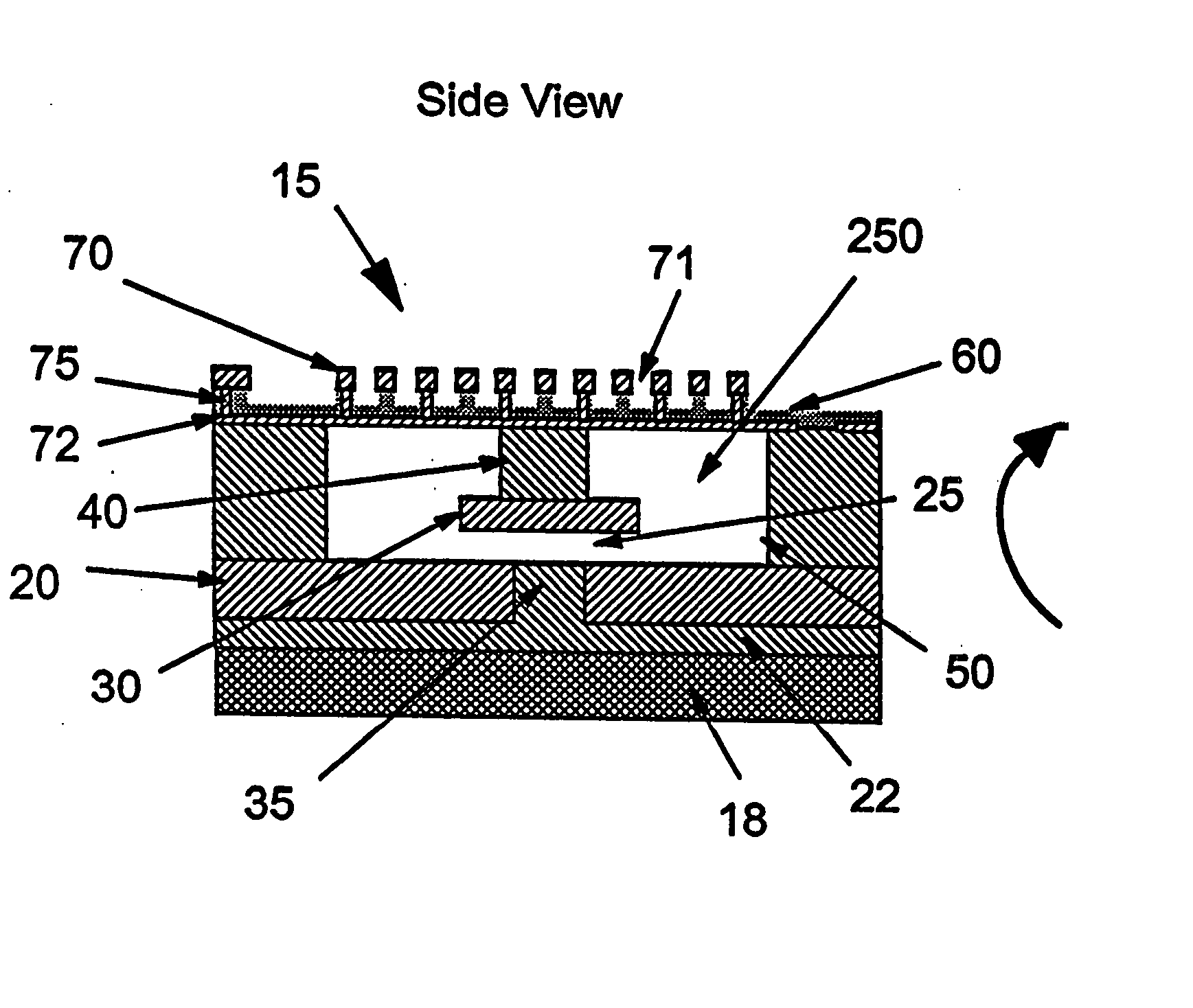
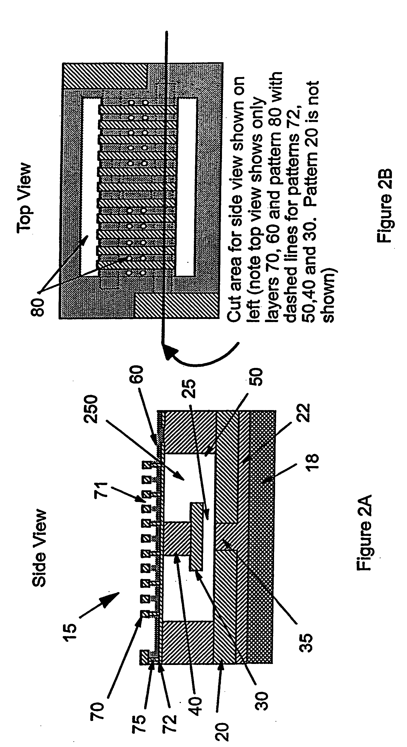
[0025] To fully illustrate the unique design of the inventive switch, a detailed description of the MEMS switch will now be described hereinafter with reference to FIGS. 2A-2B.

[0026] Device 15 is fabricated on a substrate 18 onto which a dielectric 22 is deposited with inlaid metal traces 20. This forms a surface with planar conductive electrodes separated by a dielectric region 35. Dielectric space 35 is bridged by metal contact electrode 30 when the dielectric actuator membrane 60 deflects downward and causes contact electrode 30 to touch or come in close proximity to metal traces 20. The contact formed allows an RF signal to propagate between the two metal electrodes 20 through metal contact electrode 30. Metal contact electrode 30 is within cavity 250 and physically attached to dielectric post (or plunger) 40, which in turn is physically attached to the membrane 60. Cavity 250 is bounded on the sides by dielectric standoffs 50. Also shown in FIG. 2B are access holes and slots 8...


PUM

PropertyMeasurementUnit
voltagesaaaaaaaaaa
voltageaaaaaaaaaa
conductiveaaaaaaaaaa

Abstract

A micro-electromechanical (MEM) RF switch provided with a deflectable membrane (60) activates a switch contact or plunger (40). The membrane incorporates interdigitated metal electrodes (70) which cause a stress gradient in the membrane when activated by way of a DC electric field. The stress gradient results in a predictable bending or displacement of the membrane (60), and is used to mechanically displace the switch contact (30). An RF gap area (25) located within the cavity (250) is totally segregated from the gaps (71) between the interdigitated metal electrodes (70). The membrane is electrostatically displaced in two opposing directions, thereby aiding to activate and deactivate the switch. The micro-electromechanical switch includes: a cavity (250); at least one conductive path (20) integral to a first surface bordering the cavity; a flexible membrane (60) parallel to the first surface bordering the cavity (250), the flexible membrane (60) having a plurality of actuating electrodes (70); and a plunger (40) attached to the flexible membrane (60) in a direction away from the actuating electrodes (70), the plunger (40) having a conductive surface that makes electric contact with the conductive paths, opening and closing the switch.

Description

TECHNICAL FIELD [0001] The present invention is related to micro-electromechanical system (MEMS) switches, and more particularly to a MEMS switch that allows for controlled actuation with low voltages (less than 10V) while maintaining good switch characteristics such as isolation and low insertion loss. BACKGROUND ART [0002] Wireless communication devices are becoming increasingly popular, and as such, provide significant business opportunities to those with technologies that offer maximum performance and minimum costs. A successful wireless communication device provides clean, low noise signal transmission and reception at a reasonable cost and, in the case of portable devices, operates with low power consumption to maximize battery lifetime. A current industry focus is to monolithically integrate all the components needed for wireless communication onto one integrated circuit (IC) chip to further reduce the cost and size while enhancing performance. [0003] One component of a wirel...

Claims


Application Information

Patent Timeline
Patent Type & Authority Applications(United States)
IPC IPC(8): H01H51/22B81B3/00B81C1/00G02B5/00G02B26/00G02B26/08H01H57/00H01H59/00
CPCH01H59/0009H01H2057/006
Inventor JAHNES, CHRISTOPHER V.LUND, JENNIFER L.SAENGER, KATHERINE L.VOLANT, RICHARD P.
Owner GLOBALFOUNDRIES US INC
Why Eureka
Try Eureka