Extension device for unloader

A technology of extension device and unloader, applied in the directions of transportation and packaging, loading/unloading, etc., which can solve the problems of lack of extension device and inability to adapt to large working surfaces.

Inactive Publication Date: 2013-03-06
刘国云
View PDF2 Cites 0 Cited by
  • Summary
  • Abstract
  • Description
  • Claims
  • Application Information

AI Technical Summary

Problems solved by technology

Similarly, this kind of unloading machine lacks an extension device and cannot adapt to a large working surface.

Method used


Image

  • Extension device for unloader
  • Extension device for unloader
  • Extension device for unloader

Examples


Embodiment Construction

[0023] The preferred embodiments of the present invention will be described in detail below in conjunction with the accompanying drawings, so that the advantages and features of the present invention can be more easily understood by those skilled in the art, so as to define the protection scope of the present invention more clearly.

[0024] The invention provides an extension device of an unloading machine, which can greatly expand the working range of the unloading machine.

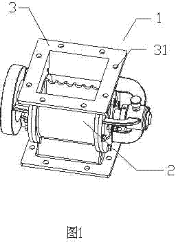
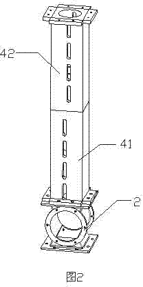
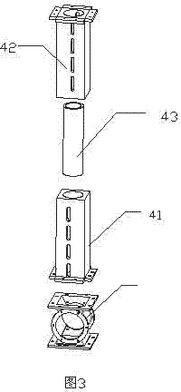
[0025] like figure 1 , figure 2 and image 3 Shown is the extension device of the unloader of the present invention, the unloader 1 includes a casing 2, the upper part of the casing 2 is provided with a mounting surface 3 for installing the extension device, and the mounting surface 3 is provided with a The opening 31 of the extension device is fixed, and the extension device includes an extension column 41 and an extension sleeve 43 .

[0026] like Figure 4 and Figure 5 As shown, the extension...


PUM


Abstract

The invention discloses an extension device for an unloader. The unloader comprises a casing. The top of the casing is provided with a mounting surface for mounting the extension device. A hole for fixing the extension device is arranged on the mounting surface. The extension device comprises an extension column and an extension sleeve. The extension column comprises a base matching with the mounting surface and a column body containing the extension sleeve. The surface of the column body is provided with elongated holes for movably fastening the extension sleeve. The elongated holes are symmetrically arranged on the side wall of the column body. The extension sleeve is a hollow cylinder. By the aid of the splittable extension device, the unloader is available in any length for users and meets the requirement for operations of large-size materials.

Description

[0001] technical field [0002] The invention relates to a kind of engineering feeding equipment, more precisely, it is a kind of unloading machine. [0003] Background technique [0004] The unloader is the main equipment for dust removal equipment, dust removal, air supply and other equipment feeding. It is suitable for feeding powdery and granular materials. It is widely used in environmental protection, metallurgy, chemical industry, grain, food and other industrial sectors. . The existing unloading machine lacks an extension device and cannot use a larger working surface. [0005] Chinese invention patent ZL 200410053406.2 discloses an unloading machine. It includes a vertical feeding device, a transfer device, a supporting device, and a rotating tower; the vertical feeding device includes a vertical feeding tube and a vertical screw feeder arranged in the tube, and the lower part of the vertical feeding tube is covered with a rotatable outer tube with spiral blades ...

Claims


Application Information

Patent Timeline
Patent Type & Authority Applications(China)
IPC IPC(8): B65G65/34B65G69/00
Inventor 刘国云
Owner 刘国云
Why Eureka
Try Eureka