Fin and base punching combination method of radiator

A combination method and technology of heat dissipation fins, applied in the direction of instruments, electrical digital data processing, digital data processing parts, etc., can solve the problems affecting the plastic deformation of the clamp rib 95, poor clamping, easy breakage, etc.

Inactive Publication Date: 2013-03-27
LEMTECH PRECISION MATERIAL (CHINA) CO LTD
View PDF3 Cites 6 Cited by
  • Summary
  • Abstract
  • Description
  • Claims
  • Application Information

AI Technical Summary

Problems solved by technology

However, during stamping and riveting, the plastic deformation part 97 of each clamping rib 95 is easier to break, and causes poor clamping
In addition, when the punch 96 punches the cl

Method used


Image

  • Fin and base punching combination method of radiator
  • Fin and base punching combination method of radiator
  • Fin and base punching combination method of radiator

Examples


Embodiment Construction

[0036] Relevant present invention is to achieve above-mentioned purpose, adopts technical means and effect thereof, enumerates feasible embodiment hereby, and cooperates accompanying drawing to illustrate as follows:

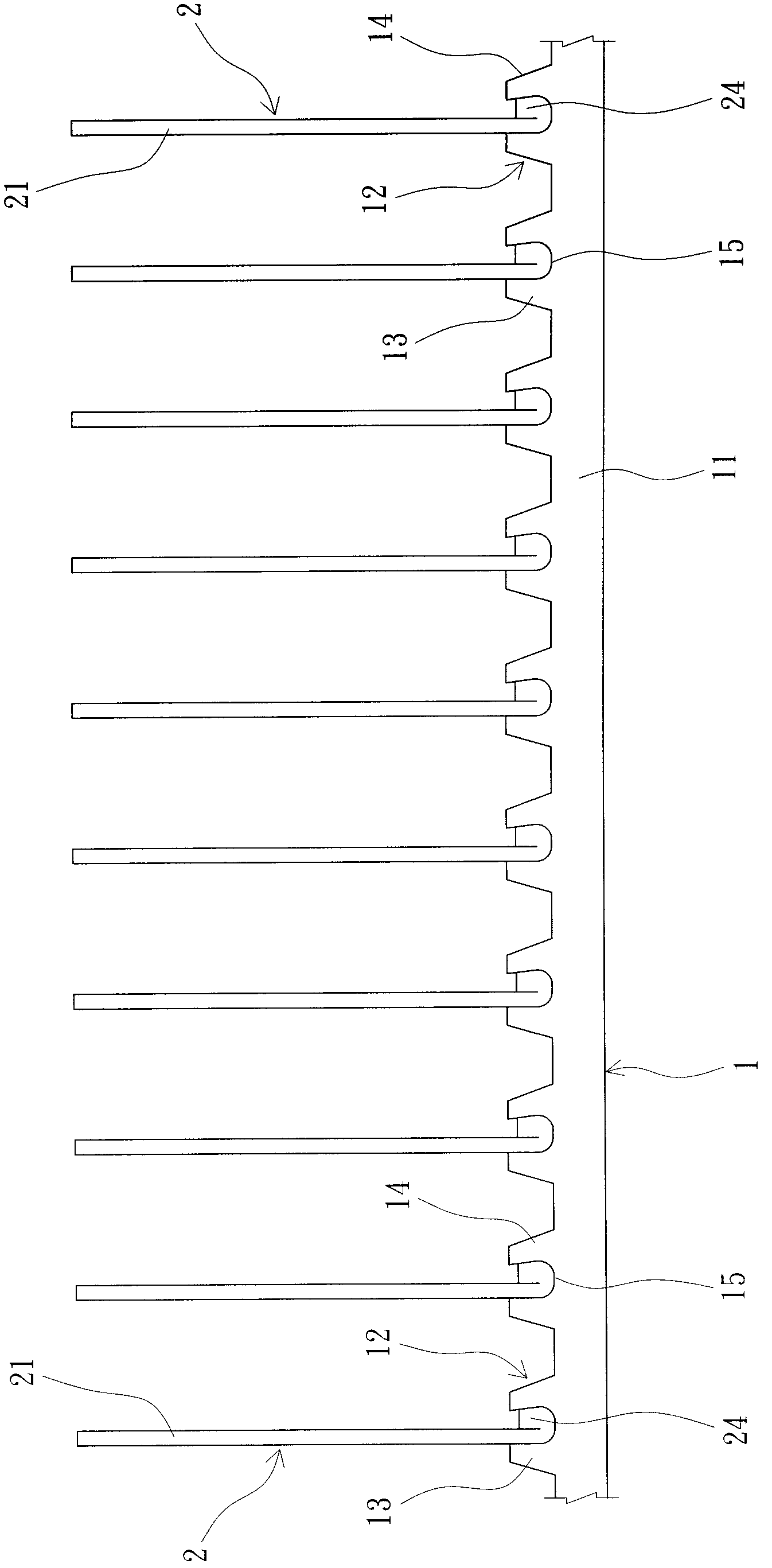
[0037] First, see image 3 , the heat sink of the present invention mainly assists the heat source of the electronic device to dissipate heat. As shown in the figure, the heat sink is inserted with a plurality of heat dissipation fins 2 arranged at equal intervals on a base 1, and then for each heat dissipation fin Sheet 2 is fixed by stamping combination.

[0038] exist image 3 , Figure 4 and Figure 5 In the preferred embodiment shown, the present invention is mainly aimed at the stamping combination method of the cooling fins 2 and the base 1 of the radiator. A plurality of positioning portions 12 are arranged at intervals, and each positioning portion 12 includes a first protruding rib 13 and an opposite second protruding rib 14 , and a positioning gro...


PUM


Abstract

The invention relates to a fin and base punching combination method of a radiator, and the method comprises the following steps that a base is manufactured; a plurality of positioning parts are arranged on the surface of a metal base body at intervals; each positioning part comprises a positioning groove; a plurality of radiating fins are manufactured, and a reversely folded piece is respectively bent on the tail ends of the metal piece bodies of the radiating fins; the tail ends of the radiating fins and the reversely folded pieces thereof are respectively inserted into the positioning grooves of the positioning parts, so that the opposite outer sides of the tail ends of the radiating fins and the reversely folded pieces thereof face both opposite sides of the positioning grooves; and a punch is used for punching the ends of the reversely folded pieces which are opposite to the radiating fins, the reversely folded pieces are punched into extruded deformation bodies with the directions of the ends being compressed, so that the extruded deformation bodies are respectively provided with an outward expanding part, so as to press the positioning grooves which are fixedly arranged on the opposite positioning parts and the opposite sides of the positioning grooves, a firmer and tighter integration effect is achieved, the processing and assembly quality is improved, and the heat transfer and dissipation effects are improved.

Description

technical field [0001] The invention relates to a method for manufacturing a heat sink, in particular to a method for stamping and combining heat dissipation fins and a base of the heat sink. Background technique [0002] With the rapid development of the computer industry, the execution speed of heat sources such as chips and central processing units (CPUs) is getting faster and faster, and the heat of the corresponding heat sources is also getting higher and higher. In order to discharge the high temperature generated by the heat source to the outside , so that the heat source can operate normally at the allowable temperature, usually a radiator with a larger area is attached to the heat overflow surface of the heat source, so as to use the multiple fins of the radiator to assist in heat dissipation. [0003] Such as figure 1 and figure 2 As shown, most of the existing heat sinks 9 include a flat base 91 and a plurality of fins 92. The base 91 and the fins 92 are made o...

Claims


Application Information

Patent Timeline
IPC IPC(8): G06F1/20
Inventor 杨煌龙
Owner LEMTECH PRECISION MATERIAL (CHINA) CO LTD
Why Eureka
Try Eureka