Axial flow fan and air conditioner

An axial flow fan and air conditioner technology, applied in air conditioning systems, lighting and heating equipment, space heating and ventilation, etc., can solve problems such as noise, reduce fan efficiency, and achieve the effect of suppressing wake flow and satisfying use.

Inactive Publication Date: 2013-04-17
LG ELECTRONICS INC
View PDF12 Cites 11 Cited by
  • Summary
  • Abstract
  • Description
  • Claims
  • Application Information

AI Technical Summary

Problems solved by technology

[0008] However, in the case of the prior art axial flow fan, since the surface defined from the hub to the tip of the blade is a curved surface, the aerodynamic drag is concentrated at the tip of the blade to cause wake flow
This reduces fan efficiency and introduces noise

Method used


Image

  • Axial flow fan and air conditioner
  • Axial flow fan and air conditioner
  • Axial flow fan and air conditioner

Examples


Embodiment Construction

[0022] Hereinafter, an axial fan and an air conditioner according to various embodiments of the present invention will be described with reference to the accompanying drawings.

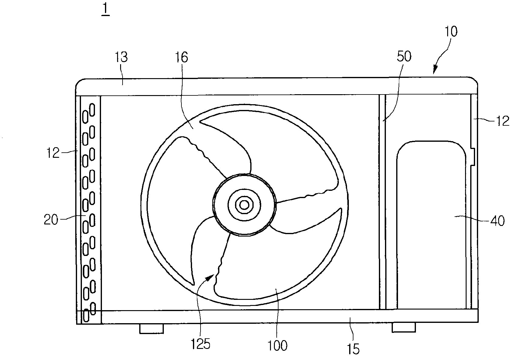
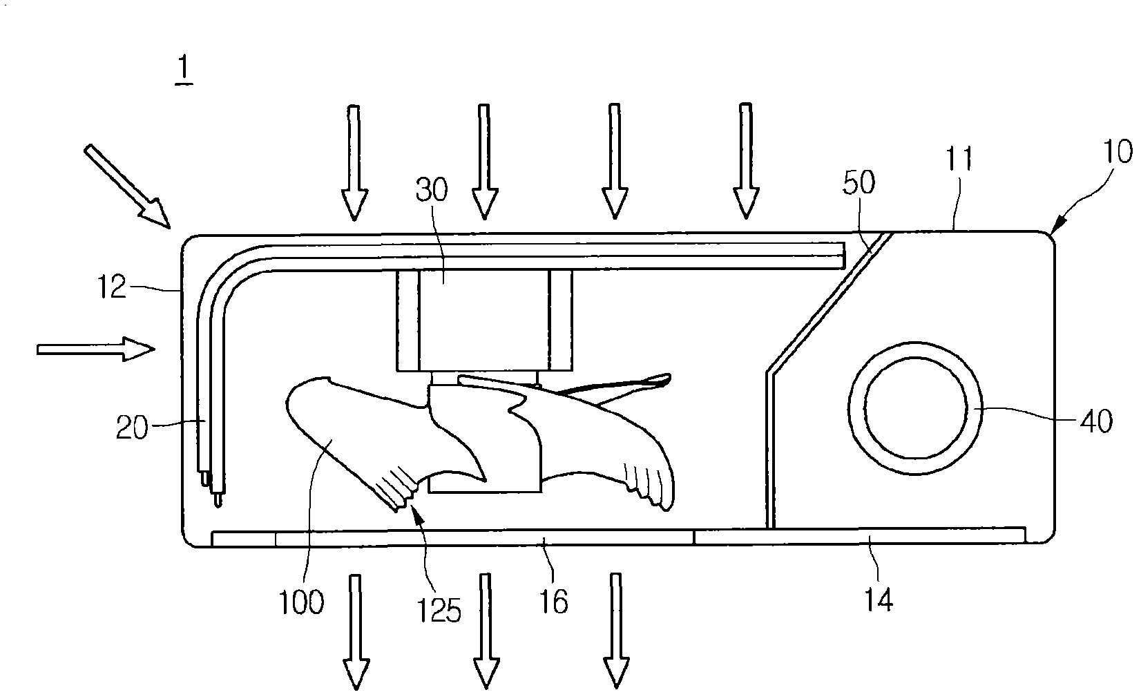
[0023] figure 1 shows a front view of the air conditioner 1 according to the first embodiment, while figure 2 A plan view of the air conditioner 1 according to the first embodiment is shown.

[0024] refer to figure 1 and figure 2 , The air conditioner 1 of the first embodiment includes a casing 10 , a heat exchanger 20 , a fan 100 , a motor 30 , a filter (not shown), a compressor 40 and a baffle 50 . In this embodiment, the air conditioner 1 may be an outdoor unit.

[0025] The housing 10 includes: a rear panel 11 constituting the rear side of the air conditioner 1; a side panel 12 coupled to the rear panel 11 for constituting the side of the air conditioner 1; a top panel 13 constituting the top side of the air conditioner 1; a panel 14, It constitutes the front side of the air conditioner 1 ...


PUM


Abstract

Provided are an axial flow fan and an air conditioner. The axial flow fan includes a plurality of blades (120). The blades (120) include corrugated parts (125) on ends thereof. The corrugated parts (125) include convex portions (125a) and concave portions (125b) that are alternately arranged.

Description

[0001] Cross References to Related Applications [0002] This application claims priority from Korean Patent Application No. 10-2011-0104368 filed on October 20, 2011, the entire contents of which are hereby incorporated by reference. technical field [0003] The present invention relates to an axial flow fan and an air conditioner. Background technique [0004] Air conditioners are used to heat or cool indoor spaces. This air conditioner includes a compressor for compressing refrigerant, a condenser for condensing refrigerant discharged from the compressor, an expansion device for expanding the refrigerant discharged from the condenser, and a compressor for evaporating the refrigerant expanded by the expansion device. Refrigerant evaporator. [0005] Both the condenser and the evaporator in an air conditioner are heat exchangers in which the refrigerant exchanges heat with the surrounding air. The condenser and the evaporator may be provided in the indoor unit and the ou...

Claims


Application Information

Patent Timeline
Patent Type & Authority Applications(China)
IPC IPC(8): F04D29/38F24F1/00
CPCF04D29/384F05D2240/304F04D29/32F04D29/38F24F5/00F24F13/00
Inventor 朴正宅许德郑载赫
Owner LG ELECTRONICS INC
Why Eureka
Try Eureka