Eureka AIR delivers breakthrough ideas for toughest innovation challenges, trusted by R&D personnel around the world.

Shoe mold rack with collision device and corresponding mounting bracket

A technology of collision device and fixing frame, which is applied in the field of joint parts and opening

Inactive Publication Date: 2013-05-08
宗占国
View PDF0 Cites 2 Cited by
  • Summary
  • Abstract
  • Description
  • Claims
  • Application Information

AI Technical Summary

Problems solved by technology

Obviously, the process has to bear labor costs

Method used


Image

  • Shoe mold rack with collision device and corresponding mounting bracket
  • Shoe mold rack with collision device and corresponding mounting bracket
  • Shoe mold rack with collision device and corresponding mounting bracket

Examples


Embodiment Construction

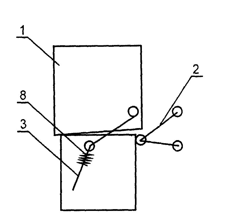
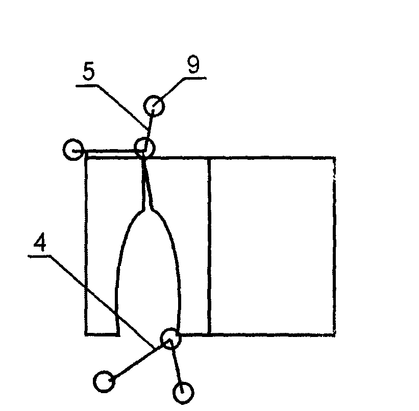
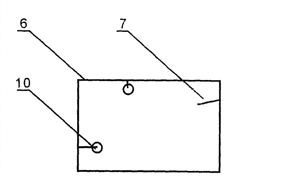
[0011] Set the lock lever a (2) and mold opening lever a (3) at the upper and lower opening and closing positions of the shoe mold frame (1), and set the locking lever b (4) and mold opening lever at the left and right opening and closing positions of the shoe mold frame (1). Lever b (5), position spring (8) and moving wheel (9) are set on the lever, and lock lever a / b (2 / 4) and mold opening lever a / b (3 / 4) are established on the fixed frame (6). 5) Corresponding angle-adjustable fixed rails (7) and fixed wheels (10).


PUM


Abstract

The invention disclose a shoe mold rack with a collision device and a corresponding mounting bracket, comprising a shoe mold rack, a latch lever, a mold opening lever, a mounting bracket and a fixed orbit. A latch lever a and a mold opening lever a are arranged at the up-and-down opening position of the shoe mold rack, a latch lever b and a mold opening lever b are arranged at the left-and-right opening position of the shoe mold rack, the lever is provided with a locating spring and a driving wheel, the mounting bracket is provided with an angle-adjustable fixed orbit and an angle-adjustable fixed wheel which respectively correspond to the latch lever a / b and the mold opening lever a / b. The technical scheme is applied to the polyurethane shoe pipeline, through the collision of the lever driving wheel on the shoe mold rack and the corresponding fixed orbit on the mounting bracket, the automatic mold opening and closing can be achieved, and two operators can be saved.

Description

[0001] The technical field [0002] The invention relates to an opening and closing part of a polyurethane assembly line shoe injection mold, in particular to a shoe mold frame with a collision device and a corresponding fixing frame. Background technique [0003] The molds of polyurethane assembly line shoes are divided into upper and lower mold bases and upper mold bases, and then divided into left and right mold bases. During operation, mold opening and mold closing must be completed by two operators. There is a semicircular lock between the upper and lower molds of the conventional mold and between the left and right molds of the upper mold, with a handle at one end, which is manually rotated to unlock and lock, and then the mold is opened and closed manually. Obviously, the process has to bear labor costs. Contents of the invention [0004] The innovation point of the present invention is: transform the shoe mold base (do not change the original shoe mold), make the m...

Claims


Application Information

Patent Timeline
IPC IPC(8): B29C45/26B29C45/64B29L31/50
Inventor 宗占国
Owner 宗占国
Why Eureka
Eureka Blog
Learn More