Inflating nozzle device

A technology of inflatable nozzles and air holes, applied in the direction of valve devices, valve operation/release devices, valve details, etc., can solve the problem of air pressure reduction of inflatable parts, and achieve the effect of improving a large amount of deflation

Active Publication Date: 2013-05-08
BETO ENG & MARKETING
View PDF9 Cites 2 Cited by
  • Summary
  • Abstract
  • Description
  • Claims
  • Application Information

AI Technical Summary

Problems solved by technology

[0007] please cooperate Figure 1C It can be seen that after the inflatable part is inflated, it is necessary to turn the wrench 95 to reset, so that the valve body 94 returns to the original point, to release the first air nozzle 93A, and to untie the clamped state of the French mouthpiece FV, and then the French mouthpiece can be released. The mouthpiece FV is pulled out, but when the wrench 95 is turned to release the valve body 94, the air release valve 98 will form a normally open state. At this time, the French mouthpiece FV has no time to pull out, and the first valve part 97A is st

Method used


Image

  • Inflating nozzle device
  • Inflating nozzle device
  • Inflating nozzle device

Examples


Embodiment Construction

[0072] In order to further explain the technical solution of the present invention, the present invention will be described in detail below through specific examples.

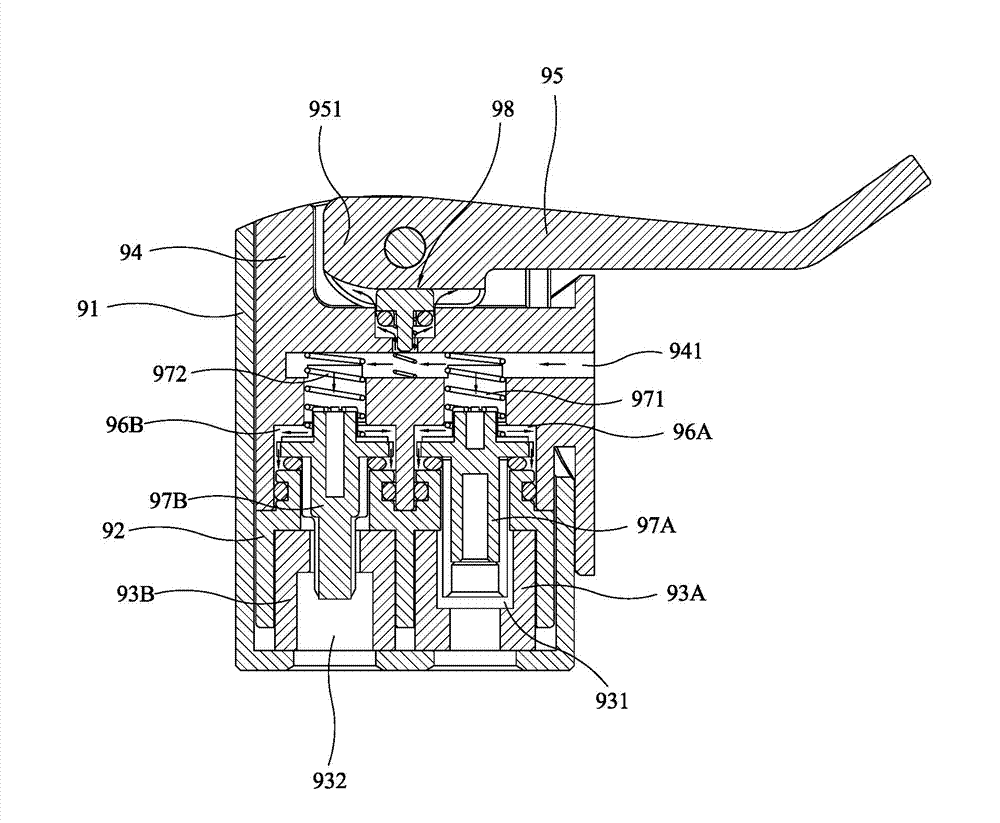
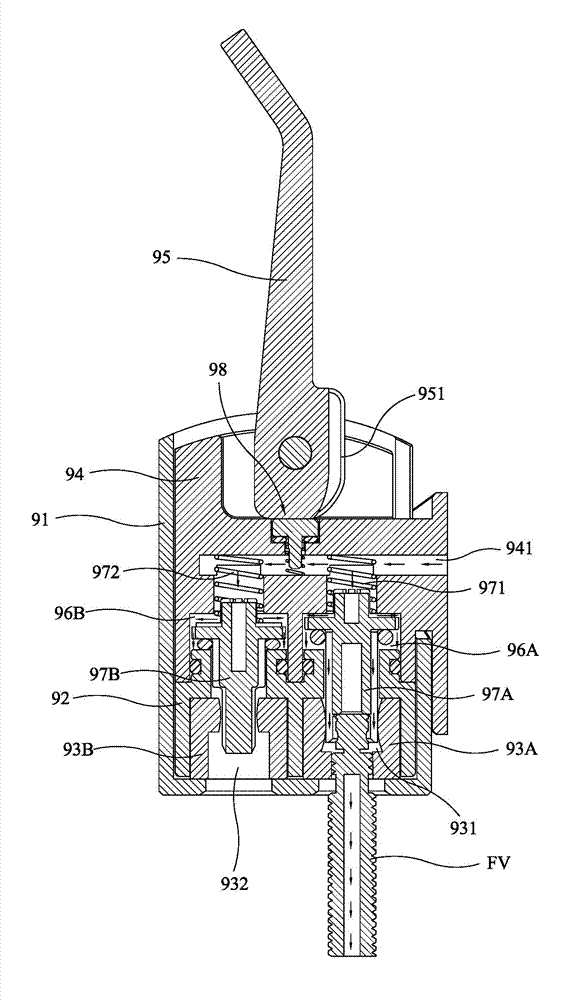
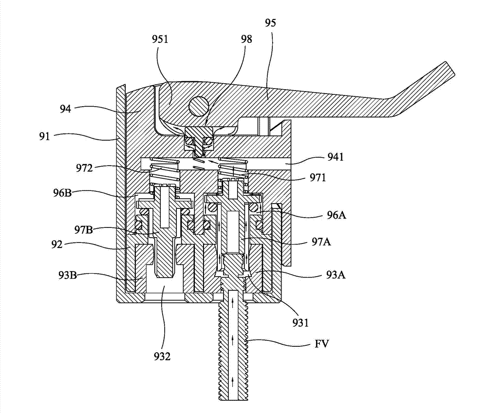
[0073] Please refer to figure 2 , image 3 and Figure 4A , the present invention includes:

[0074] A head seat 10, which extends upwards around a bottom plate 11 with a trunk portion 12 for defining an upwardly transparent assembly chamber 13 inside, the bottom plate 11 is longitudinally provided with a first air hole 11A connecting the inside and outside of the assembly chamber 13, and a second Air hole 11B, a tip hole 14 runs through the opposite sides of the top edge of the head seat 10 transversely, and a gap 15 is recessed at the rear end, and a sleeve 16 with a sleeve hole is externally connected to the trunk portion 12 under the gap 15, and the trunk portion 12 is also provided with an air hole 17 that runs through the assembly chamber 13 within the range of the sleeve hole of the sleeve 16, so tha...


PUM


Abstract

The invention discloses an inflating nozzle device. A first air nozzle, a cylinder, a valve block, and a lever are sequentially disposed in a head seat from bottom to top. The first air nozzle is provided with a first positioning hole allowing a Guillemin coupling to be inserted in. The cylinder is provided with a first cylinder hole communicated with the first positioning hole. A counter pressure passageway communicated with the first cylinder hole is formed at the top of the cylinder. A first valve is mounted in the first cylinder hole. A first spring is disposed at the top end of the first valve. The valve block is available for positioning the top end of the first spring and is provided with an inlet passage allowing inflation of an inflator and upper and lower containing holes communicated with the inlet passage. The lower containing hole is communicated with the top of the counter pressure passageway and receives a stopper. A normally open relief valve is mounted in the upper containing hole. One end of the lever is pivoted to the top edge of the head seat through a pin, and a cam capable of limiting the top end of the valve block is formed on the periphery of the pivoted end of the lever. The cam can be turned to switch off the relief valve so as to continuously push the valve block to move down to clamp and inflate the Guillemin coupling.

Description

technical field [0001] The invention relates to an inflatable device, in particular to an inflatable nozzle device. Background technique [0002] Please see Figure 1A , which discloses an inflatable nozzle device that can prevent "air plugs" from forming inside. The inflatable nozzle device is equipped with a cylinder 92 at the bottom of the head seat 91, a first air nozzle 93A pressed by the cylinder 92, a cylinder The second air nozzle 93B pressed by body 92, a wrench 95 with a cam 951 is pivoted on the top of the head seat 91, and a valve body 94 is installed between the cylinder body 92 and the wrench 95, so that the cam 951 of the wrench 95 can drive the valve. The body 94 restricts and presses the cylinder body 92 downwards, so that the cylinder body 92 can act on the two air nozzles 93A, 93B, such as Figure 1B As shown, the positioning hole 931 of the first nozzle 93A clamps the French nozzle FV of the inflatable part, and the positioning hole 932 of the second noz...

Claims


Application Information

Patent Timeline
IPC IPC(8): F16K15/20F16K31/524
Inventor 王罗平
Owner BETO ENG & MARKETING
Why Eureka
Try Eureka