Emergency escape device applicable to security windows

A technology of escape device and anti-theft window, which is applied in door/window protection device, anti-theft, window/door, etc. It can solve the problems of slow emergency response, threat to life safety, and easily affected power system, and achieve high reliability, The effect of fast emergency response and ensuring life safety

Inactive Publication Date: 2015-03-11
四川博华工程材料有限公司
View PDF7 Cites 0 Cited by
  • Summary
  • Abstract
  • Description
  • Claims
  • Application Information

AI Technical Summary

Problems solved by technology

[0004] Chinese patent application number: 201110198322.8 discloses a lifting anti-theft window, which consists of a window frame, a protective net, and a lifting mechanism. There are uprights symmetrically arranged in the left and right frames, and the uprights pass through the cross bar and a number of metal rings from bottom to top. , the upper and lower ends of the column are fixedly connected with the upper and lower frames respectively, the two ends of the upper frame are provided with fixed pulleys, the middle and left side of the lower frame are provided with a mesh structure, the two ends of the horizontal wire rope are connected with the metal ring, and the vertical The two ends of the wire rope are fixedly connected with the upper frame and the cross bar respectively, and the wire rope is lowered and retracted by the lifting mechanism to realize the purpose of opening and closing the anti-theft window. It is possible to escape, but once a fire occurs, the power system is easily affected, causing the lifting mechanism to fail to work normally, which makes it very difficult to open the anti-theft window, and the emergency response is slow, threatening people's lives.

Method used


Image

  • Emergency escape device applicable to security windows
  • Emergency escape device applicable to security windows
  • Emergency escape device applicable to security windows

Examples


Embodiment Construction

[0022] The present invention will be further described below in conjunction with the accompanying drawings, but the protection scope of the present invention is not limited to the following description.

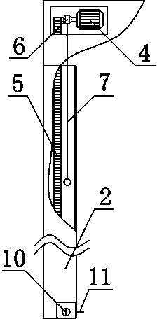
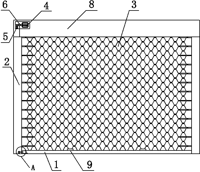
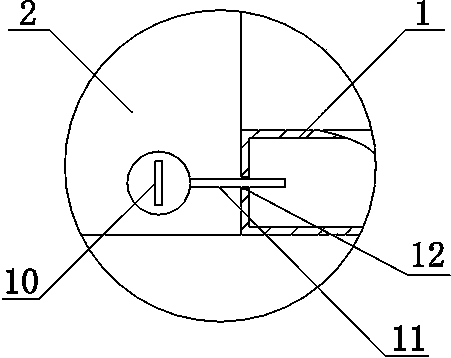
[0023] Such as figure 1 , figure 2 and image 3 As shown, an emergency escape device suitable for anti-theft windows, it includes a lower frame 1, a side frame 2 and an anti-theft window mesh 3, the bottom of the anti-theft window mesh 3 is fixed on the lower frame 1, and the two sides of the anti-theft window mesh 3 The side slide is installed inside the side frame 2, which also includes a motor 4, a clutch control device, and a mechanical locking device. The motor 4 is a variable speed motor, and the power output end of the motor 4 is connected to the chain 5 for transmission, and the chain 5 is connected for transmission with the lower frame 1; The clutch control device includes a clutch device 6 and a traction rope 7, the clutch device 6 is arranged on the motor 4, the...


PUM


Abstract

The invention relates to an emergency escape device applicable to security windows. The emergency escape device comprises a lower border (1), a side border (2), a security window mesh (3), a motor (4), a clutch control device and a mechanical locking device, the clutch control device comprises a clutch device (6) and a pulling rope (7), the clutch device (6) is arranged on the motor (4) and connected with the pulling rope (7), the mechanical locking device comprises a mechanical lock (10), a mechanical bolt (11) and a lock hole, the mechanical lock (10) is arranged on the lower portion of the side border (2) and is in transmission connection with the mechanical bolt (11), the lock hole is arranged on the left end face of the lower border, and the mechanical bolt (11) is matched with the lock hole. The emergency escape device has the advantages that under emergency situations, indoor staff can open the security windows within 15s, and the emergency escape device is fast in emergency, high in reliability, convenient to operate and independent of electric power.

Description

technical field [0001] The invention relates to the technical field of anti-theft devices, in particular to an emergency escape device suitable for anti-theft windows. Background technique [0002] Today's home anti-theft protection systems can be roughly divided into two categories. One is electronic protection, which is often referred to as intelligent protection. Most of them are used for public protection in hotels, banks and residential quarters. The other type is visible physical protective devices. The traditional cage-type anti-theft window is a protective device that can be seen everywhere at present, but this cage-type anti-theft window is a closed whole. Once there is danger inside, escape and rescue are extremely difficult. Difficulty, although in recent years, escape door is also made on anti-theft window, but this cage type anti-theft window is exposed to the outside for a long time, makes the lock that is used for locking escape door corroded, and can't be op...

Claims


Application Information

Patent Timeline
Patent Type & Authority Patents(China)
IPC IPC(8): E06B5/11E06B9/02E06B9/68
Inventor 雷新生
Owner 四川博华工程材料有限公司
Why Eureka
Try Eureka