
Magnetic coupling wireless electric energy transmission device for converter valve

A technology of wireless power transmission and magnetic coupling, which is applied in the field of converter valves, can solve the problems of inability to realize electrical isolation, large power supply device, and high insulation level, and achieve high-efficiency installation and commissioning, high insulation level, and realization of installation and commissioning effects

Pending Publication Date: 2020-05-01
GLOBAL ENERGY INTERCONNECTION RES INST CO LTD +2
View PDF0 Cites 1 Cited by
  • Summary
  • Abstract
  • Description
  • Claims
  • Application Information

AI Technical Summary

Problems solved by technology

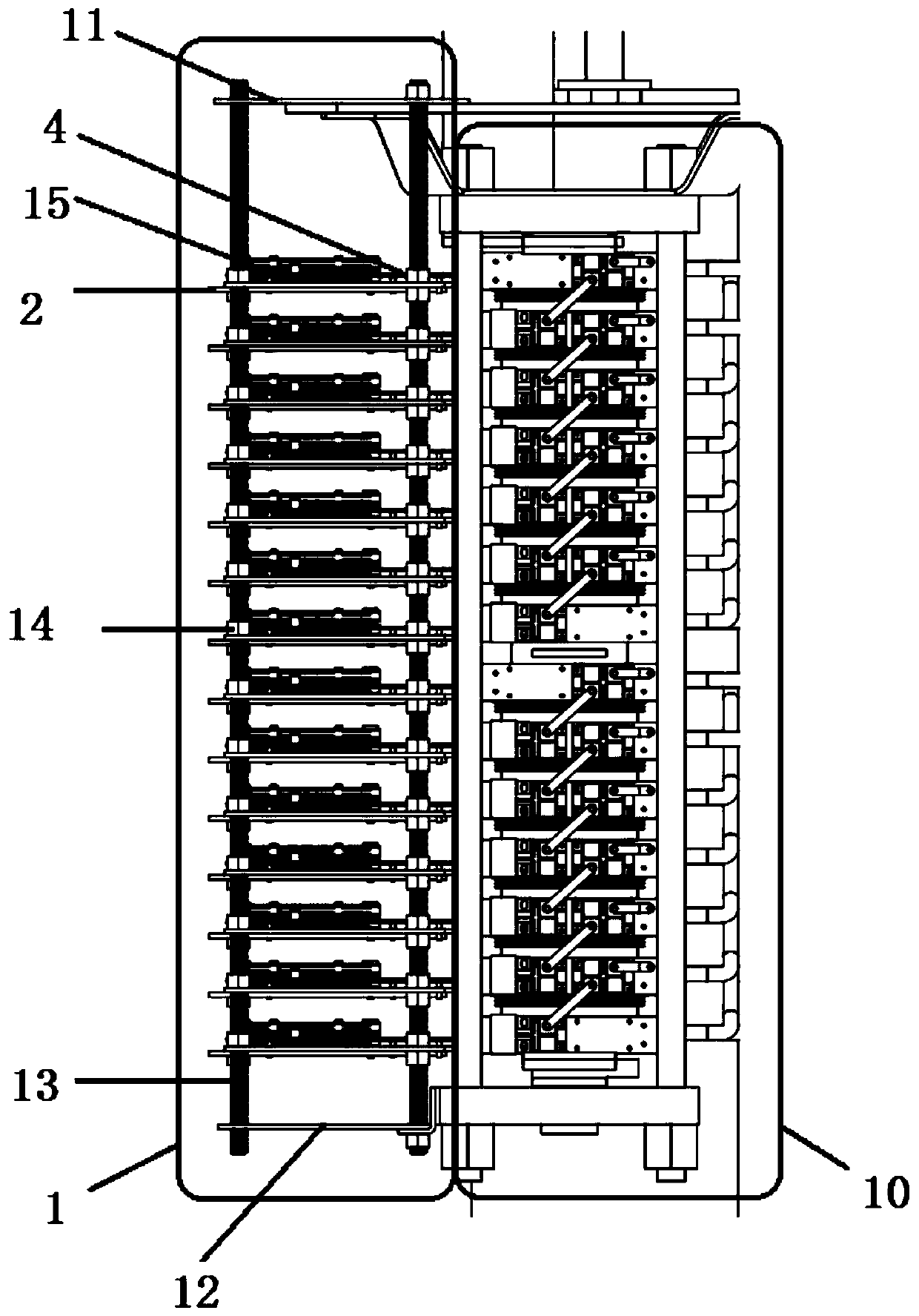
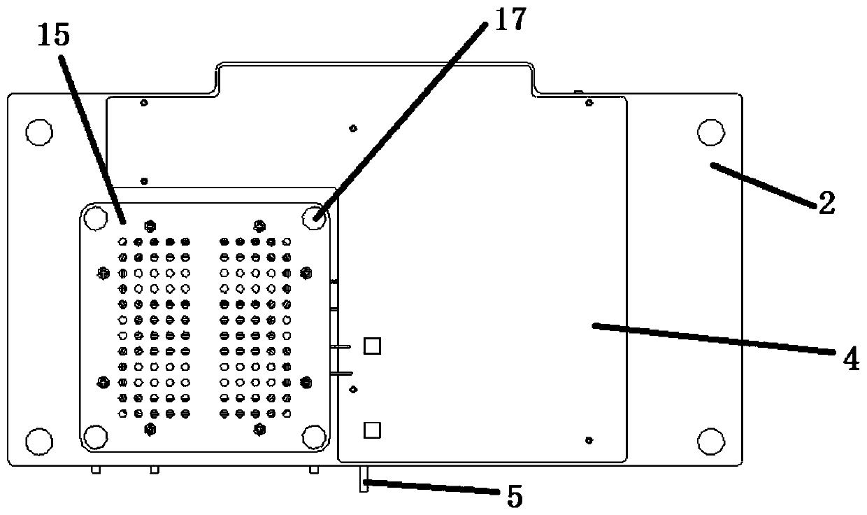
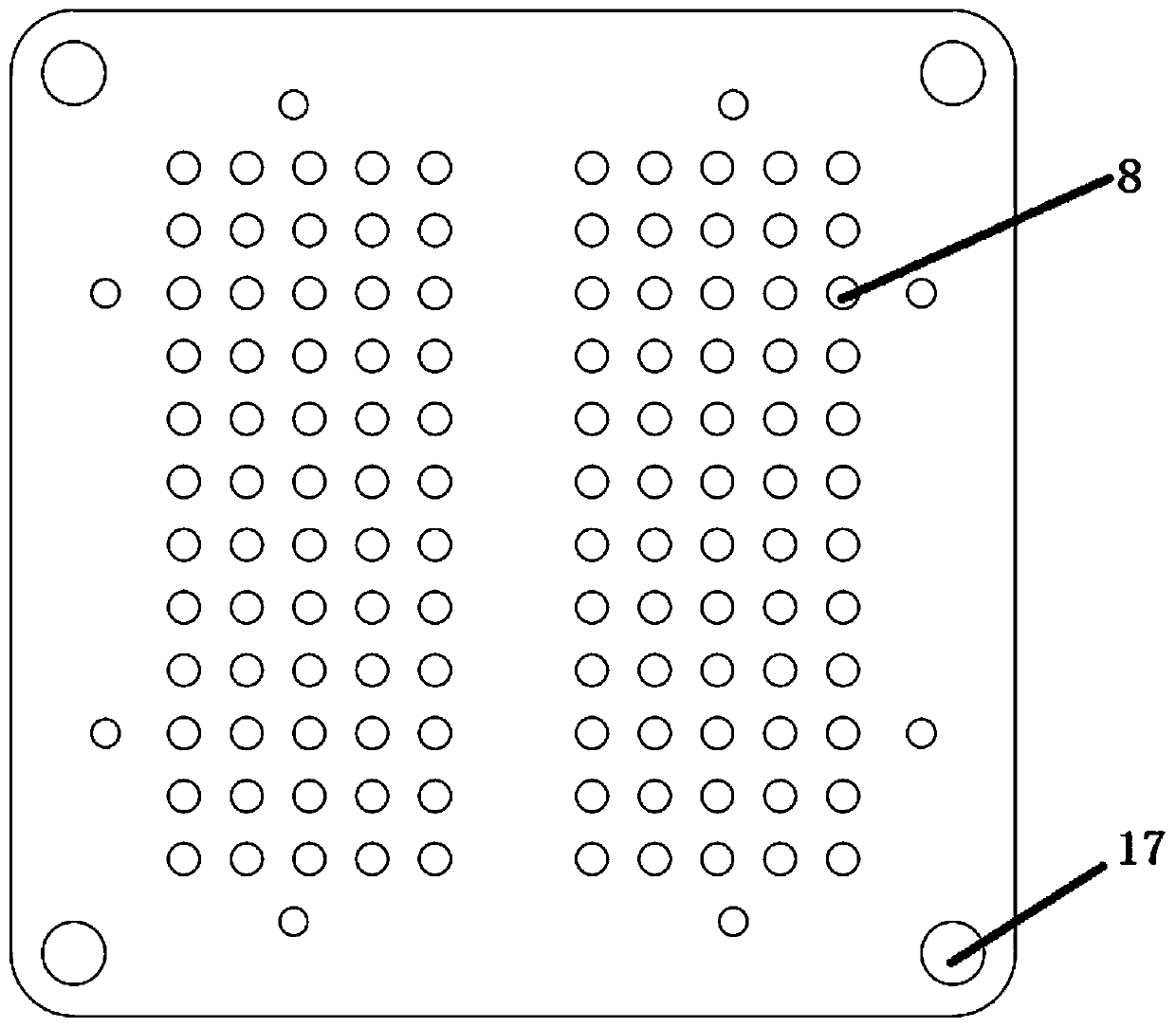
[0005] In order to overcome the above-mentioned shortcomings in the prior art that electrical isolation cannot be realized, the power supply device has a large volume and a low insulation level, the present invention provides a magnetic coupling wireless power transmission device for a converter valve, which includes a top plate (11), a bottom plate (12 ) and the energy sending coil (15) and the driving pallet (2) arranged between the top plate (11), the base plate (12); the energy sending coil (15) is fixed on the driving pallet (2); The device is connected to the converter valve (10) through the top plate (11) and the bottom plate (12), and electrical isolation can be realized between the device and the converter valve, the overall volume is small, and the insulation level is high

Method used


Image

  • Magnetic coupling wireless electric energy transmission device for converter valve
  • Magnetic coupling wireless electric energy transmission device for converter valve
  • Magnetic coupling wireless electric energy transmission device for converter valve

Examples


Embodiment Construction

[0039] The present invention will be described in further detail below in conjunction with the accompanying drawings.

[0040] An embodiment of the present invention provides a magnetically coupled wireless power transmission device for a converter valve, such as figure 1 As shown, the upper end of the converter valve 10 is a positive high-voltage end, the lower end is a negative high-voltage end, and the middle position is a low-voltage ground potential. The embodiment of the present invention provides a magnetically coupled wireless power transmission device including a top plate 11, a bottom plate 12, and a top plate 11 and a bottom plate. The energy transmission coil 15 between 12 and the drive pallet 2;

[0041] The energy sending coil 15 is fixed on the driving pallet 2;

[0042] The device is connected to the diverter valve 10 through the top plate 11 and the bottom plate 12, and both the top plate 11 and the bottom plate 12 are connected to the diverter valve 10 throu...


PUM


Abstract

The invention provides a magnetic coupling wireless electric energy transmission device for a converter valve. The magnetic coupling wireless electric energy transmission device comprises a top plate(11), a bottom plate (12), an energy transmitting coil (15) and a driving supporting plate (2), wherein the energy transmitting coil (15) and the driving supporting plate (2) are arranged between thetop plate (11) and the bottom plate (12); and the energy transmitting coil (15) is fixed on the driving supporting plate (2). The device is connected with the converter valve (10) through the top plate (11) and the bottom plate (12), electrical isolation can be achieved, the overall size is small, and the insulation level is high; the coil shell is made of organic glass or epoxy resin, visibilityand ornamental value of the coil are guaranteed, overall insulation can be achieved, the pull rod and the fastening nut can be made of metal materials or insulation materials, and the insulation levelis high. Bolt-free and outside operation fixing is realized, and high-efficiency installation and debugging can be realized; the area of the coil can be effectively reduced, and the overall size of the magnetic coupling wireless electric energy transmission device is further reduced.

Description

technical field [0001] The invention relates to the technical field of converter valves, in particular to a magnetic coupling wireless power transmission device for converter valves. Background technique [0002] With the improvement of the voltage level and transmission capacity of the High Voltage Direct Current (HVDC) system, power electronic equipment such as converter valves has been widely used, and press-fit IGBT devices are gradually being used in flexible DC converter valves. . [0003] In the prior art, the drive in the converter valve is generally powered by the following methods: (1) the high voltage of the converter valve is converted into a low voltage by a high-voltage self-energy device to realize the power supply of the drive; (2) High-voltage cables supply high-voltage power to the driver; (3) A transformer with an iron core is used to realize the isolated power supply and energy transmission of the driver. [0004] However, there are the following disadv...

Claims


Application Information

Patent Timeline
Patent Type & Authority Applications(China)
IPC IPC(8): H02J50/10H02J50/40H02J50/70H02J3/36
CPCH02J3/36H02J50/10H02J50/40H02J50/70Y02E60/60
Inventor 石秋雨周哲苏铁山李芳义邓占锋赵国亮李卫国刘海军袁婷婷康伟乔光尧
Owner GLOBAL ENERGY INTERCONNECTION RES INST CO LTD
Learn More