Adjustable Portable Light

A portable and lamp frame technology, applied in portable lighting devices, components of lighting devices, semiconductor devices of light-emitting elements, etc., can solve problems such as difficulty and trouble in removing light sources

Active Publication Date: 2013-07-17
SUREFIRE LLC
View PDF3 Cites 5 Cited by
  • Summary
  • Abstract
  • Description
  • Claims
  • Application Information

AI Technical Summary

Problems solved by technology

However, the adjustability of the lamp relative to its base makes it difficult and cumbersome to remove the light source in the event the user wishes to use it as a handheld flashlight

Method used


Image

  • Adjustable Portable Light
  • Adjustable Portable Light
  • Adjustable Portable Light

Examples


Embodiment Construction

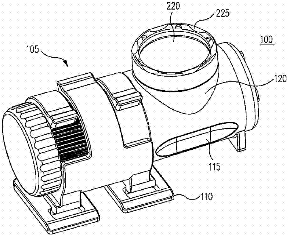
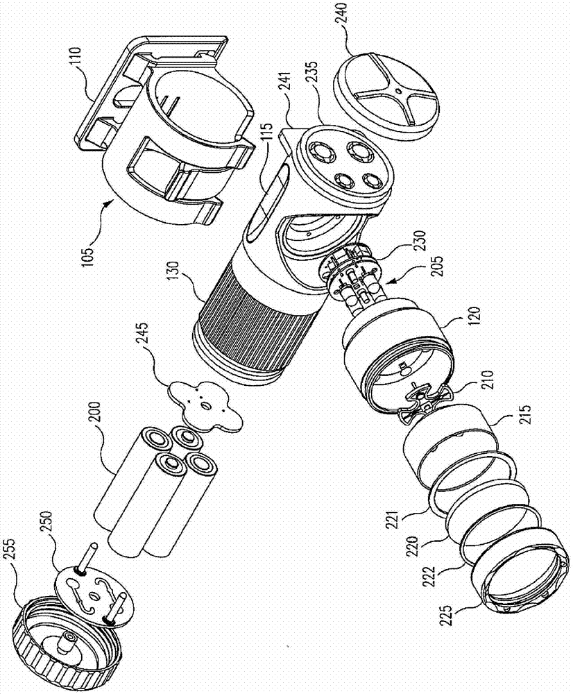
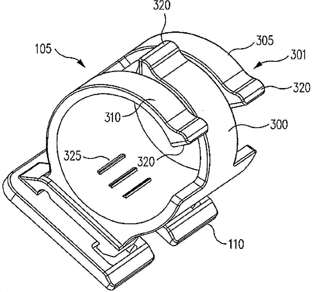
[0019] Now turning to the attached image, figure 1 An example portable light 100 is shown adjustably held in a bracket assembly 105 which is in turn secured to a base 110 . Bracket assembly 105 holds cylindrical housing 115, which can be placed on figure 2 is better seen in the corresponding exploded view of . Housing 115 provides a longitudinally extending housing for, for example, four AA batteries 200 . A flashlight bezel 120 protrudes radially from the housing 115 . Light frame 120 receives a plurality of LEDs 205 , which are mounted on LED board 210 . Light frame 120 also receives reflector 215 and lens 220 as is conventional in the flashlight art. Retainer 225 is threadably received by light frame 120 to secure lens 220 and associated seals 221 and 222 to light frame 120 . Because the light frame 120 is directed radially with respect to the longitudinal axis of the housing 115, light will also be projected radially with respect to this longitudinal axis.

[0020]...


PUM


Abstract

A portable light includes: a cylindrical housing having a longitudinal axis and receiving a bezel and a lamp for projecting a light radially away from the longitudinal axis; and a cradle assembly (105) including a clamp for receiving the cylindrical housing, wherein the clamp includes a plurality of features (325) for engaging selected ones of corresponding features (130) on the cylindrical housing to secure the cylindrical housing at a selected rotational position about its longitudinal axis with regard to the cradle assembly.

Description

[0001] Related applications [0002] This patent application claims priority and benefit to US Provisional Patent Application No. 61 / 586,699, filed January 13, 2012, the contents of which are hereby incorporated by reference in their entirety. This patent application claims priority and benefit to U.S. Utility Application No. 13 / 737,403, filed January 9, 2013, the contents of which are hereby incorporated by reference in their entirety. technical field [0003] The present application relates to portable lights, such as headlamps and flashlights, and more particularly, to portable lights adapted to be spatially adjustable about a base. Background technique [0004] Portable lights using light emitting diodes (LEDs) are rapidly replacing conventional lighting sources such as incandescent light bulbs. LEDs are significantly more efficient than incandescent light bulbs, and thus provide greater lighting power and battery life. Also, LEDs are generally less fragile and theref...

Claims


Application Information

Patent Timeline
IPC IPC(8): F21L4/00F21V17/10F21Y101/02
CPCA45F2200/0566B62J6/02F21V33/0008B62J6/00F21V17/02F21L4/027B62J11/00F21V17/168A45F5/02F21Y2101/02F21L4/04F21Y2115/10B62J6/03
Inventor 约翰·W·马修斯罗纳德·S·吉布森迈克尔·D·安德森迈克尔·D·皮乔塔玄·阮
Owner SUREFIRE LLC
Why Eureka
Try Eureka