Safety limiting device used for push-pull window

A technology of limit device and sliding window, applied in electric alarm locks, building locks, buildings, etc., can solve problems such as hidden safety hazards and thieves entering the room.

Active Publication Date: 2013-09-18
洪毅
View PDF6 Cites 13 Cited by
  • Summary
  • Abstract
  • Description
  • Claims
  • Application Information

AI Technical Summary

Problems solved by technology

[0003] The defect of the prior art is that only the sliding window in the fully closed position can be locked. When the window is opened to a certain width, since the opening width of the window can be changed by pushing and pulling the inner glass 501 or the outer glass 502, there is a great security. Hazards, such as thieves who may enter the house through the window, and accidents caused by children climbing out of the window

Method used


Image

  • Safety limiting device used for push-pull window
  • Safety limiting device used for push-pull window
  • Safety limiting device used for push-pull window

Examples


Embodiment 1

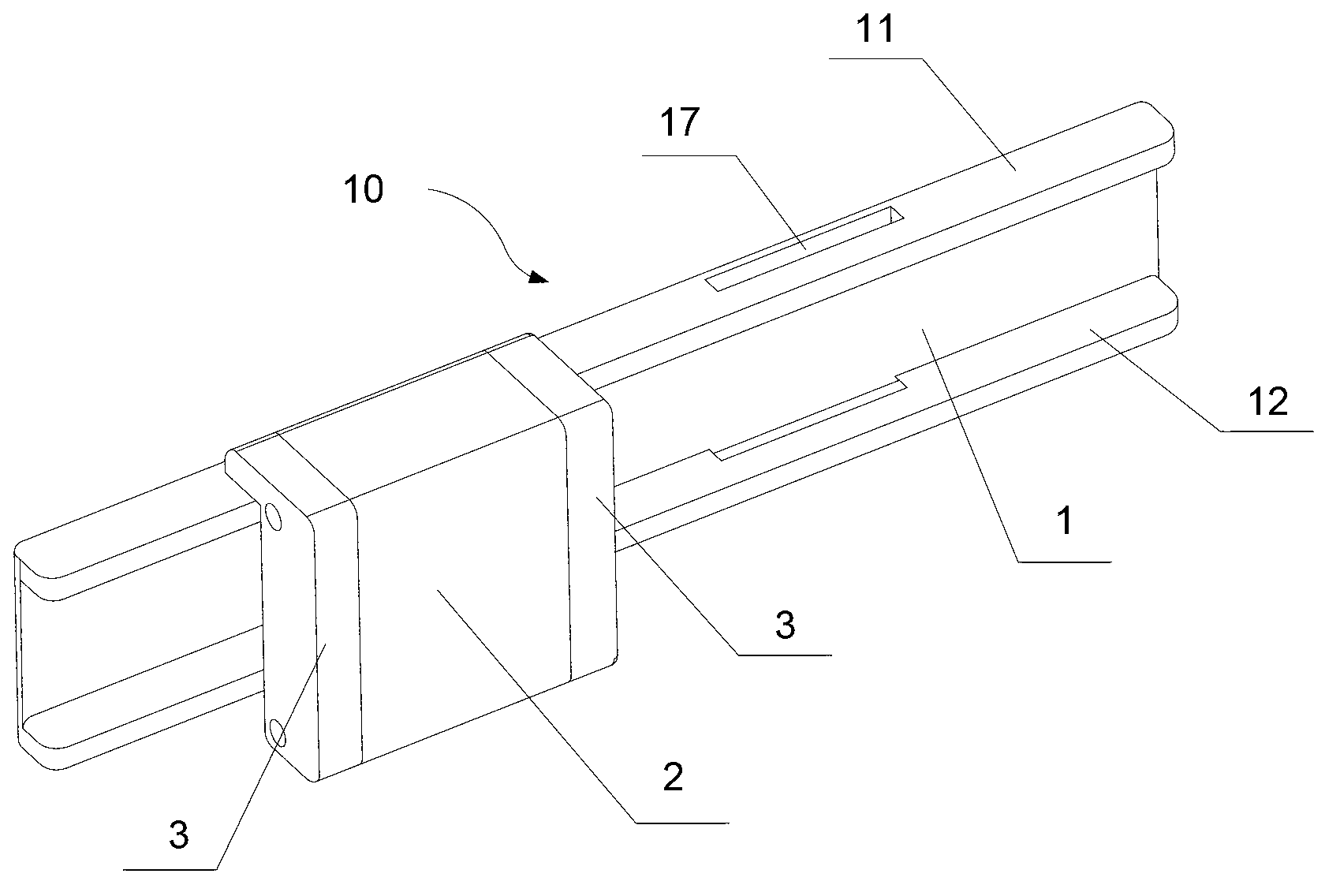
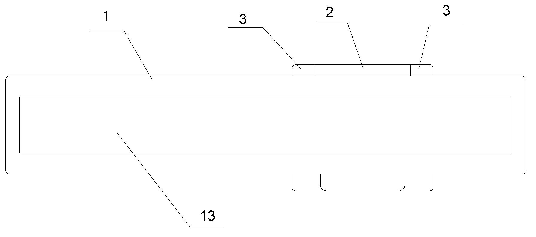
[0035] Figure 1-Figure 4 It shows the structure of the safety limit device for sliding windows according to Embodiment 1 of the present invention, Figure 5 It shows the situation of installing the safety limit device for sliding windows of the first embodiment on the sliding windows.

[0036] Wherein, the sliding window 500 includes relative inner glass 501 and outer glass 502, which is the same as the structure of the prior art, as Figure 1-Figure 5 As shown, the safety limit device 10 for sliding windows in this embodiment includes a support plate 1 attached to the inner side of the outer glass 502 by bonding or suction cup absorption, and a limit stop fixed on the support plate 1 2; wherein, the thickness of the support plate 1 is less than the gap between the inner glass 501 and the outer glass 502, the sum of the thicknesses of the support plate 1 and the stopper 2 is greater than the gap between the inner glass 501 and the outer glass 502, like this, Such as Figur...

Embodiment 2

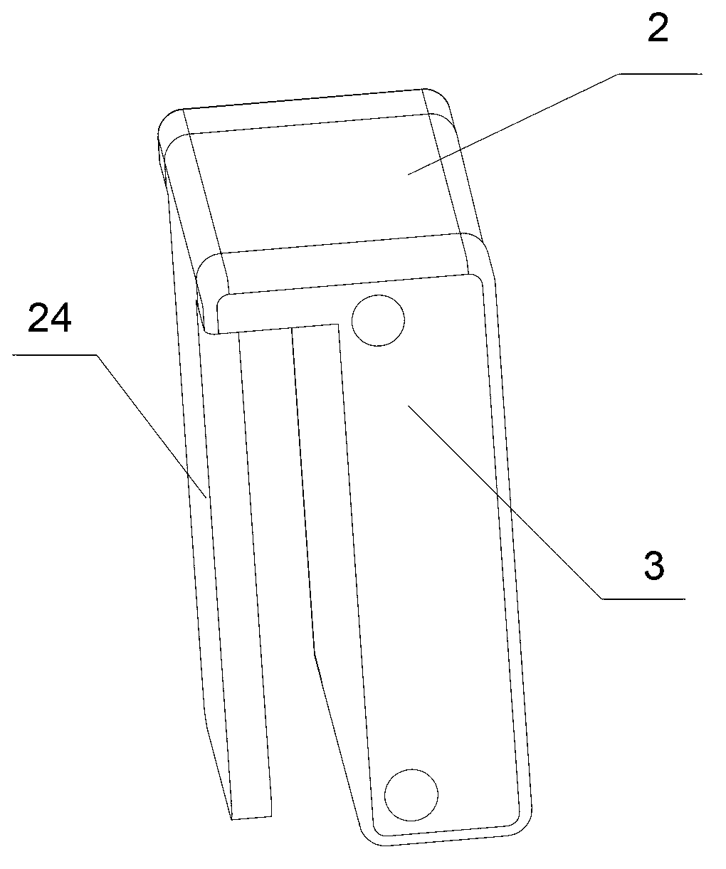
[0045] Such as Figure 6-Figure 9 As shown, the main difference between the second embodiment and the first embodiment is that the shape of the main body 21 is different. The main body 21 is made of elastic material and has a "U"-shaped structure with an opening facing the side of the support plate 1. The plates 24 are provided at both ends of the main body portion 21 and protrude outward thereof. In this embodiment, a solution in which the clamping plate 24 is integrally formed with the main body portion 21 is preferred. When installing, press the main body part 21 to make its opening smaller, release the clamping plate 24 when it is aligned with the clamping hole 17 on the support plate 1, and the clamping plate 24 enters the clamping hole 17 to realize smooth assembly. Those skilled in the art should understand that, in this embodiment, the elastic material used for the main body part 21 should have certain hardness, such as: hard plastic, wood, metal and so on.

[0046] ...

Embodiment 3

[0048] Such as Figure 10 and Figure 11 As shown, similar to the first embodiment, the main body portion 21 of the limit block 2 is also in the shape of a cuboid. The difference between the third embodiment and the first embodiment is that the side of the main body 21 close to the support plate 1 is attached with a mounting plate 241, and the mounting plate 241 and the main body 21 can be connected by screws, or can be bonded and screwed. The way of connection is to securely connect the mounting plate 241 to the main body 21 of the limit block 2 , and the clamping plate 24 is telescopically arranged at the upper and lower ends of the mounting plate 241 . In addition, it also includes a lock core 8 for controlling the expansion and contraction of the clamping plate 24 , and the main body 21 is provided with an accommodating hole (not shown in the figure) for accommodating the lock core 8 . When the limit block 2 is installed on the support plate 1, the locking plate 24 is re...


PUM


Abstract

The invention discloses a safety limiting device used for a push-pull window, wherein the push-pull window comprises a piece of inner glass and a piece of outer glass which are arranged symmetrically left and right, the safety limiting device comprises a support plate and a limiting stop block, wherein one side of the support plate is adhered to the outer side of the piece of inner glass or the inner side of the piece of outer glass in a bonding or sucking disc adsorbing way, and the limiting stop block is arranged on the other side of the support plate; and the thickness of the support plate is smaller than a gap between the piece of the inner glass and the piece of the outer glass, and the thicknesses of the support plate and the limiting stop block are larger than the gap. The safety limiting device provided by the invention has the benefits as followings: control to relative displacement between the piece of the inner glass and the piece of outer glass is achieved through the limiting stop block so as to limit the maximal opened width of the push-pull window, safety can be achieved under the condition of ensuring ventilation, children are prevented from climbing out of the window, burglars are prevented from entering from the window, and normal window opening cannot be influenced when the limiting stop block is demounted. Moreover, the way of bonding or adsorbing to glass ensures nondestructive mounting.

Description

technical field [0001] The invention relates to a safety limit device for a sliding window, in particular to a safety limit device for limiting the opening width of an inner glass or an outer glass. Background technique [0002] Such as Figure 16 As shown, a traditional sliding window 500 includes left and right inner glass 501 and outer glass 502, wherein the inner glass 501 is also called an inner fan, and the outer glass 502 is also called an outer fan. By pushing the inner glass 501 or the outer glass 502 to move horizontally, the window can be opened to a certain width to facilitate ventilation. The inner glass 501 and outer glass 502 of some sliding windows 500 can move horizontally, and one of the inner glass 501 and outer glass 502 of some sliding windows 500 is fixedly set, and the other is set to be horizontally movable, and can be moved horizontally by pushing and pulling. The movable door can be opened to a certain width. In the sliding window 500 of the prior...

Claims


Application Information

Patent Timeline
Patent Type & Authority Applications(China)
IPC IPC(8): E05B65/08E05B45/06
Inventor 洪毅
Owner 洪毅
Why Eureka
Try Eureka