Remote control method and system for master station system and station end system

A station-side and master-station technology, which is applied in the field of remote control systems between the master station system and the station-side system, can solve problems such as false control, incorrect association between remote control points and remote control objects, etc., so as to improve reliability, eliminate hidden dangers of false remote control, The effect of preventing false remote control

Active Publication Date: 2016-12-28
JIANGMEN POWER SUPPLY BUREAU OF GUANGDONG POWER GRID
View PDF5 Cites 0 Cited by
  • Summary
  • Abstract
  • Description
  • Claims
  • Application Information

AI Technical Summary

Problems solved by technology

However, in the process of daily maintenance, due to work mistakes and pressing the wrong remote control point, the association between the remote control point and the remote control object will appear in the master station system. will miscontrol other remote objects

Method used


Image

  • Remote control method and system for master station system and station end system
  • Remote control method and system for master station system and station end system
  • Remote control method and system for master station system and station end system

Examples


Embodiment 1

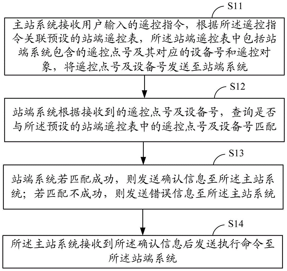
[0035] like figure 1 As shown, it is a schematic flow chart of the remote control of the master station system and the station-end system in an embodiment of the present invention. This embodiment illustrates the present invention from the interaction between the master station system and the station-end system, including the following steps:

[0036] S11. The master station system receives the remote control instruction input by the user, and associates the preset station-side remote control table according to the remote control command. The station-side remote control table includes the remote control point number and its corresponding equipment number and remote control Object, send the remote point number and equipment number to the station system;

[0037] S12. The station-side system checks whether the received remote control point number and device number match the remote control point number and device number in the preset station-side remote control table;

[0038] S...

Embodiment 2

[0047] This embodiment illustrates the processing process of the error in the association between the remote control point number and the remote control object in the station remote control table of the master station system;

[0048] The following table is a schematic form of the station-side remote control meter:

[0049]

[0050] As shown in the above table, due to the negligence of the automation personnel, when associating the remote control object, the remote control object "#1 high switch" is associated with the point number "2". Since the device number "101" corresponds to the remote control object, it does not There will be changes. When performing remote control on "#1 variable height switch", when this technology is not applied, the master station system only sends the remote point number "2" to the station-side system, and the station-side system returns confirmation after confirming that the point number exists Signal, after the remote control is executed, it ...

Embodiment 3

[0052] This embodiment illustrates the process of processing errors in the sequence of station-side remote control meters in the station-side system;

[0053] The following table is another schematic form of the remote control meter at the station:

[0054]

[0055] As shown in the table above, due to operational errors in the station system, the remote control table is inconsistent with the master station system. When the "#1 variable height switch" is remotely controlled, when this technology is not applied, the master station system only sends the remote control point number "1 "To the station-side system, after confirming the existence of the point number, the station-side system returns a confirmation signal, and after the remote control is executed, it will operate the remote control object "#1 high 01 isolation switch", resulting in misoperation. After applying this technology, the master station system will send the remote point number "1" and the device number "101...


PUM


Abstract

The invention provides a remote control method for a main station system and a station terminal system. The remote control method comprises the following steps that: the main station system receives a remote control instruction input by a user and associates the remote control instruction with a preset station terminal remote control sheet according to the remote control instruction, wherein the station terminal remote control sheet comprises remote control point numbers, equipment numbers corresponding to the remote control point numbers and remote control objects which are in the station terminal system, and the main station system sends the remote control point numbers and the equipment numbers to the station terminal system; the station terminal system inquires whether the remote control point numbers and the equipment numbers are matched with those in the preset station terminal remote control sheet according to the received remote control point numbers and the received equipment numbers; if the received remote control point numbers and the received equipment numbers are matched with those in the preset station terminal remote control sheet, the station terminal system sends confirm information to the main station system, otherwise, the station terminal system sends mistake information to the main station system; and the main station system sends an execution command to the station terminal system after receiving the confirm information. The invention also provides a remote control system for the main station system and the station terminal system. The station terminal system provided by the invention can check the received remote control point number so as to prevent mis-remote-control.

Description

technical field [0001] The invention relates to the technical field of power grid dispatching automation, in particular to a remote control method for a master station system and a station end system, and a remote control system for a master station system and a station end system. Background technique [0002] At present, the use of remote control technology for power grids is very common, and most substations have realized unattended operation. The monitoring work of the substation is concentrated in the monitoring center, and the monitoring personnel implement remote monitoring and control of the substation through the dispatching automation master station (abbreviation: master station) system and the substation automation (abbreviation: station end) system. At present, the communication protocols between the main station system and the station-side system mainly adopt IEC101 and IEC104, and there are also some other communication protocols. However, no matter what kind ...

Claims


Application Information

Patent Timeline
Patent Type & Authority Patents(China)
IPC IPC(8): G08C17/02G08C19/00H04Q9/00
Inventor 黄国政陈兴尧吴洪波郑广勇
Owner JIANGMEN POWER SUPPLY BUREAU OF GUANGDONG POWER GRID
Why Eureka
Try Eureka