
Self-insulation concrete composite building block casting box and use method thereof
A composite block and concrete technology, which is applied in the field of block molds, can solve the problems of time-consuming and laborious operation, inconvenient assembly and disassembly, and high manufacturing cost, and achieve the effect of high brick-making efficiency, low production cost and good quality
- Summary
- Abstract
- Description
- Claims
- Application Information
AI Technical Summary
Problems solved by technology
Method used
Image

Examples
Embodiment Construction
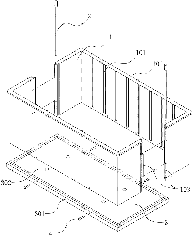
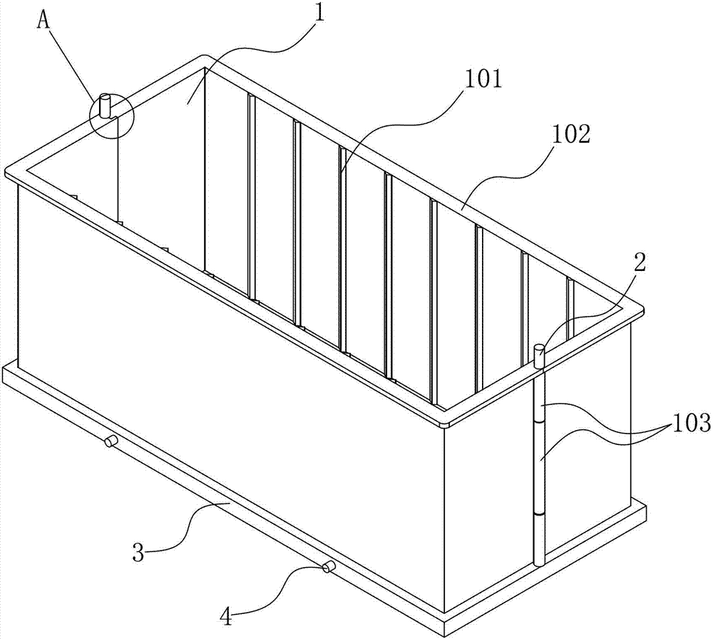
[0019] Now combined Figure 1~3 , To further describe the present invention.
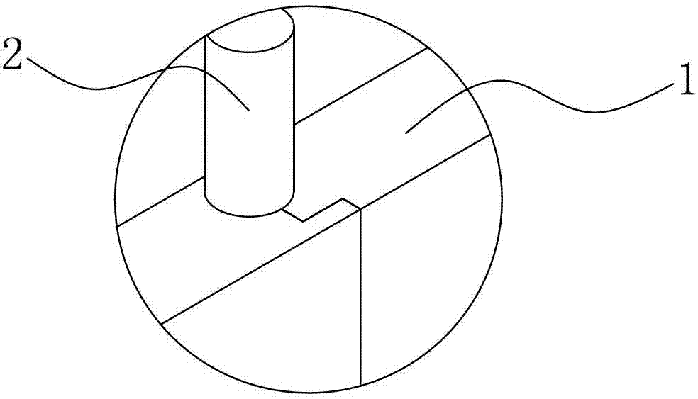
[0020] Such as figure 1 , figure 2 As shown, the self-insulating concrete composite block formwork is composed of a cubic frame connected to a rectangular bottom plate 3. The upper and lower ends of the frame are open and are formed by connecting two complementary side plates 1. The specific structure is: the side plates are in the shape of "[", and the complementary ends of the two side plates are image 3 The shown concave and convex surfaces are combined, each complementary end of the two side plates is provided with a pin hole seat 103, and when the two side plates are complementarily combined, the pin hole seat of one side plate is aligned with the pin hole seat of the other side plate. The pin hole seat of the pin hole is formed with a tapered pin hole that gradually decreases from top to bottom, and the two side plates are connected to the tapered pin hole through the plug pin 2 to achieve comp...
PUM
 Abstract
Description
Claims
Application Information