Injection molding machine

A technology of injection molding machine and mold clamping force, which is applied in the field of injection molding machines and can solve the problem that the detection results of sensors are not fully utilized.

Inactive Publication Date: 2013-10-23
SUMITOMO HEAVY IND LTD
View PDF5 Cites 13 Cited by
  • Summary
  • Abstract
  • Description
  • Claims
  • Application Information

AI Technical Summary

Problems solved by technology

[0004] Although various sensors are installed in injection molding machines to obtain information related to injection molding, the detection results of these sensors are not fully utilized

Method used


Image

  • Injection molding machine
  • Injection molding machine
  • Injection molding machine

Examples


Embodiment Construction

[0027] Hereinafter, modes for implementing the present invention will be described with reference to the drawings. In each of the drawings, the same or corresponding components are given the same or corresponding symbols and descriptions thereof are omitted.

[0028] (mold clamping device)

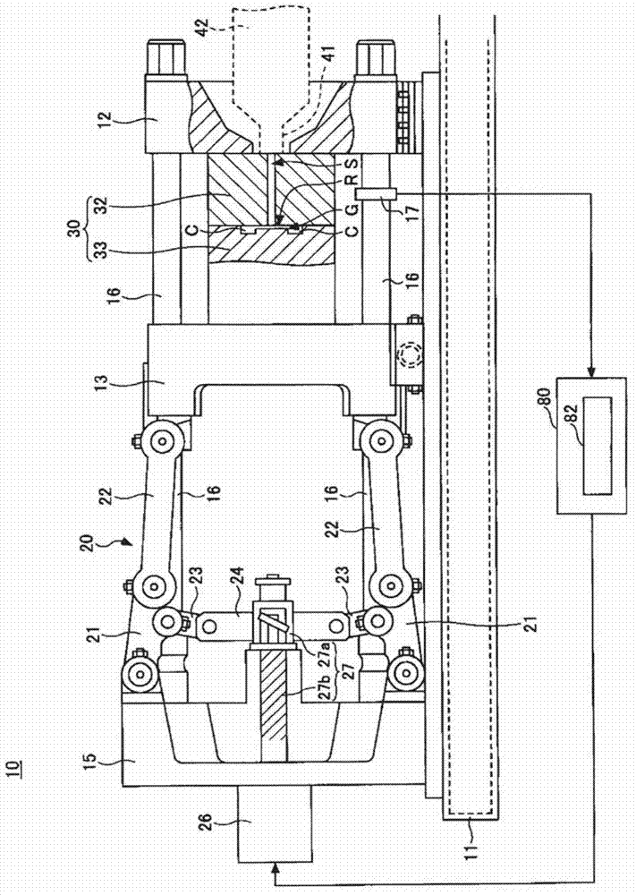
[0029] figure 1 It is a figure which shows the clamping apparatus of the injection molding machine which concerns on one Embodiment of this invention. figure 1 Indicates the clamping status. In the description of the mold clamping device, the moving direction of the movable platen when the mold is closed is referred to as the front, and the direction of movement of the movable platen when the mold is opened is described as the rear.

[0030] The injection molding machine 10 includes: a frame 11; a fixed platen 12 fixed to the frame 11; A plurality of (for example four) connecting rods 16 are erected between the fixed platen 12 and the toggle support member 15 .

[0031] The injection m...


PUM


Abstract

An injection molding machine (10) is provided that includes a clamping force sensor (17) that detects a clamping force of a mold (30), and a clamping force monitoring unit (82) that monitors a detected value of the clamping force sensor (17) and calculates a first mold open distance and / or a second mold open distance. The first mold open distance is calculated based on the difference between the maximum value of the detected values obtained during an injection process and a pressure holding process and the detected value obtained at the start of the injection process. The second mold open distance that is calculated based on the difference between the detected value obtained at the end of the pressure holding process and the detected value obtained at the start of the injection process.

Description

technical field [0001] The present invention relates to injection molding machines. Background technique [0002] The injection molding machine manufactures molded products by filling the cavity space of the mold unit with molten resin and curing it. The mold device is composed of a fixed mold and a movable mold, and a cavity space is formed between the fixed mold and the movable mold when the mold is closed. The molded product formed in the cavity space is taken out from the movable mold after the mold is opened (for example, refer to Patent Document 1). [0003] Patent Document 1: International Publication No. 2005 / 068155 [0004] Although various sensors are installed in injection molding machines to obtain information related to injection molding, the detection results of these sensors are not fully utilized. Contents of the invention [0005] The present invention has been made in view of the above problems, and an object of the present invention is to provide an i...

Claims


Application Information

Patent Timeline
IPC IPC(8): B29C45/64B29C45/76
CPCB29C45/661B29C2945/76234B29C45/80B29C2945/76869B29C2945/76391B29C2945/76933B29C45/7653B29C2945/76013B29C2945/76481B29C45/76B29C45/768B29C45/77B29C2945/76096B29C2945/76384B29C2945/76408B29C2945/76645
Inventor 德能龙一西村优
Owner SUMITOMO HEAVY IND LTD
Why Eureka
Try Eureka