Differential transformer type control bar position detector

A control rod position and differential transformer technology, applied in nuclear reactor monitoring, reactor, nuclear power generation, etc., can solve the problems of non-contact position monitoring device principle selection difficulties, etc., to achieve convenient disassembly and installation, reliable and stable installation, and easy manufacturing Effect

Inactive Publication Date: 2013-12-25
NUCLEAR POWER INSTITUTE OF CHINA
View PDF5 Cites 10 Cited by
  • Summary
  • Abstract
  • Description
  • Claims
  • Application Information

AI Technical Summary

Problems solved by technology

However, considering the installation and disassembly problems during maintenance, the position monitoring device is best arranged outside the press

Method used


Image

  • Differential transformer type control bar position detector
  • Differential transformer type control bar position detector
  • Differential transformer type control bar position detector

Examples


Embodiment Construction

[0015] The present invention will be described in detail below in conjunction with the accompanying drawings and specific embodiments.

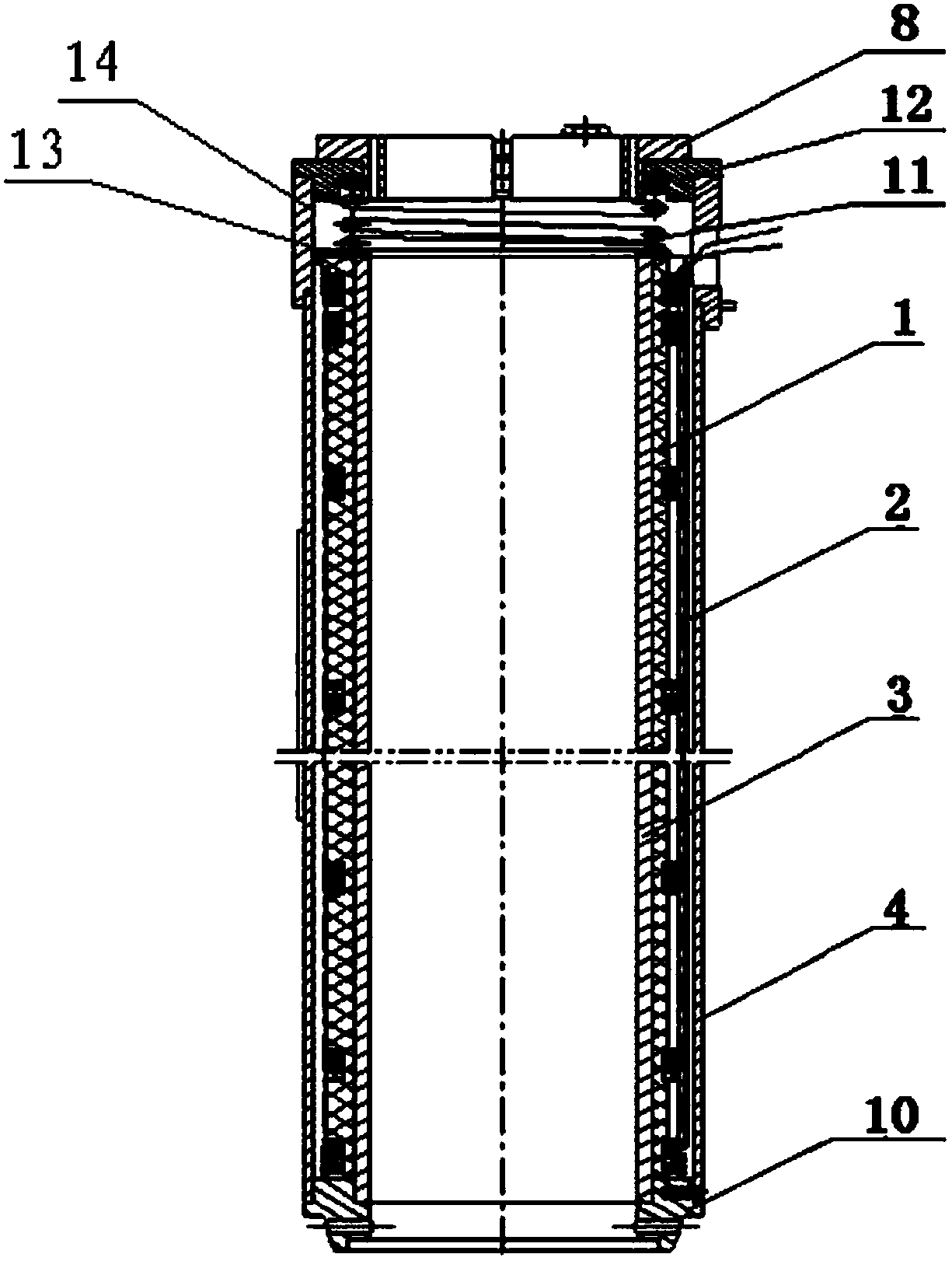
[0016] Such as Figure 1a , Figure 1b and figure 2 As shown, the bobbin 1 is a thin-walled cylinder made of non-magnetic material, 0Cr19Ni9 is used in this embodiment. Ring grooves are respectively symmetrically processed on the upper, lower and middle parts of the coil bobbin 1 .

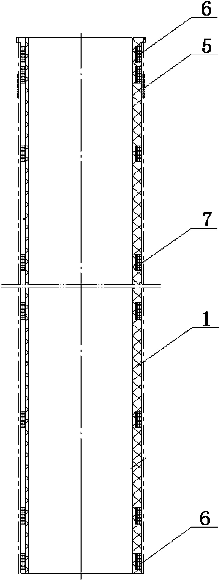
[0017] The rod position detection coil 2 is composed of a primary coil 5, two compensation coils 6 and several secondary coils 7. In this embodiment, there are 6 secondary coils 7, and the compensation coils 6 are wound on the upper and lower ends of the bobbin 1. The secondary coil 7 is wound in the annular groove in the middle of the bobbin 1 . The primary coil 5 is wound on the outer wall of the entire coil bobbin 1 to cover the entire coil bobbin 1, and the coil end is wound in multiple layers to ensure that both sides of the secondary coil at the end are...


PUM


Abstract

The invention relates to the technical field of control bar drive mechanism in a reactor structure, particularly discloses a differential transformer type control bar position detector. The detector comprises coil frames, wherein ring-shaped grooves are respectively and symmetrically arranged at the upper end, at the lower end and in the middle of each coil frame, and a bar position detecting coil is arranged outside each coil frame. The bar position detecting coils comprise compensating coils wound in the ring-shaped grooves at the upper end and the lower end of the coil frames, secondary coils wound in the ring-shaped groove in the middle of the coil frame, and a primary coil wound the outer wall of the whole coil frame. An inner barrel body is arranged in the coil frame and an outer barrel body is arranged outside the coil frame. The primary coil is led out from the outer barrel body. The primary coil passes through whole travel of a drive rod, can obtain bar falling time by collecting induced voltage signals during a bar falling process, can monitor in real-time control rod actual position, facilitates performing of drive mechanism bar falling experiments, and supports and protects the bar position detecting coil due to the fact that the inner barrel body and the outer barrel body are designed in and outside the coil frame.

Description

technical field [0001] The invention belongs to the technical field of a control rod driving mechanism in a reactor structure, and in particular relates to a control rod position detection device. Background technique [0002] The control rod position detector (rod position detector for short) is an important component of the control rod drive mechanism, which is used to monitor the actual position and drop time of the control rods in the reactor, and provide control and protection interlock signals. [0003] Conventional position monitoring devices, in terms of their association with moving parts, mainly include contact and non-contact types. Among them, the contact type position monitoring device has the simplest structure, such as pull-wire / pull-rod displacement based on the principle of resistance. sensor. The contact position monitoring device can easily and quickly realize the displacement measurement of the linear moving parts, but since the use of this kind of devic...

Claims


Application Information

Patent Timeline
IPC IPC(8): G21C17/10
CPCY02E30/30
Inventor 余志伟杨方亮陈西南于天达罗英李红鹰杨柯彭航杨晓晨谢细明胥春燕李庆许斌唐向东杨博
Owner NUCLEAR POWER INSTITUTE OF CHINA
Why Eureka
Try Eureka