Rotating shaft welding jig, rotating shaft welding worktable and automatic rotating shaft welding system

A welding fixture and workbench technology, applied in welding accessories, welding equipment, welding equipment, etc., can solve problems such as cracks, slag inclusions, uneven welding, high labor intensity, etc., to save costs and procedures, improve work High efficiency and good welding fusion

Active Publication Date: 2014-01-15
ZHEJIANG CHINT ELECTRIC CO LTD
View PDF9 Cites 19 Cited by
  • Summary
  • Abstract
  • Description
  • Claims
  • Application Information

AI Technical Summary

Problems solved by technology

At present, the processing method of the shaft usually adopts low-efficiency forging, casting, convenient manual gas shielded welding equipment and technology, brazing, and efficient robot semi-automatic gas shielded welding. Because of its simple and easy operation, it is widely used in coal mines and rail vehicles. , automobiles, low-voltage electrical appliances and other industries have played a great role, but in many occasions, it is difficult to obtain good welding results with this equipment and technology, and its shortcomings are mainly manifested in high labor intensity, high energy consumption, and long cycles. , low efficiency; it is easy to cause many weld joints, uneven welding, large splashes, and poor product consistency; some parts will produce undercutting and local severe ablation; and cracks, slag inclusions, and Defects such as incomplete penetration and virtual welding

Method used


Image

  • Rotating shaft welding jig, rotating shaft welding worktable and automatic rotating shaft welding system
  • Rotating shaft welding jig, rotating shaft welding worktable and automatic rotating shaft welding system
  • Rotating shaft welding jig, rotating shaft welding worktable and automatic rotating shaft welding system

Examples


Embodiment Construction

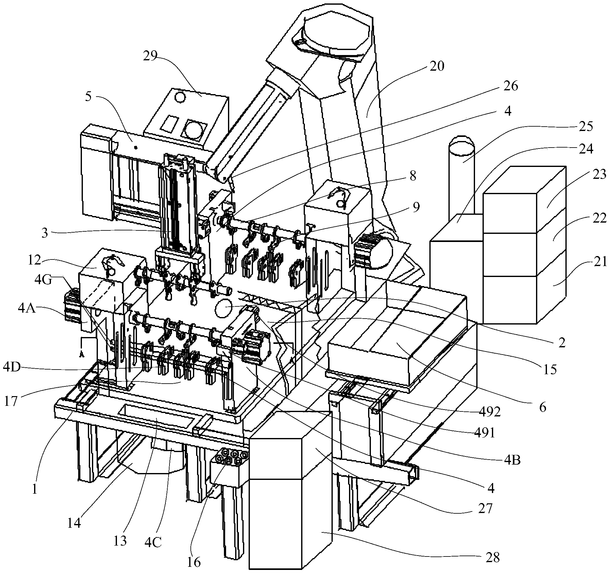
[0041] Such as figure 1 As shown, the present invention provides an automatic welding system for a rotating shaft, including a rotating shaft welding workbench and a robot welding system. The rotating shaft welding workbench and the robot welding system cooperate with each other to realize the welding of the rotating shaft and the rotating shaft components. The rotating shaft welding workbench is used for clamping and fixing the rotating shaft and rotating shaft components to be welded, and the robot welding system is used for performing welding work. The two ends of the rotating shaft welding workbench are equipped with a feeding position and a welding position, which can realize feeding and welding at the same time to improve work efficiency, wherein one end of the welding robot 20 located in the robot welding system is a welding position, and the other end is a feeding position An operation panel 16 is arranged on one side of the loading position, and the control panel 16 i...


PUM


Abstract

The invention discloses a rotating shaft welding jig, a rotating shaft welding worktable and an automatic rotating shaft welding system. The rotating shaft welding jig comprises a rotating shaft clamp and a component fixing device, wherein the rotating shaft clamp is used for clamping a rotating shaft, and the component fixing device is used for fixing a rotating shaft component which needs to be welded to the rotating shaft. The rotating shaft clamp comprises a rotating shaft supporting and rotating mechanism and a rotating shaft supporting and clamping mechanism, wherein the rotating shaft supporting and rotating mechanism and the rotating shaft supporting and clamping mechanism are used for clamping the two ends of the rotating shaft respectively. The component fixing device is arranged between the rotating shaft supporting and rotating mechanism and the rotating shaft supporting and clamping mechanism and comprises a rotating shaft component clamping part and a clamping driving part. The rotating shaft component clamping part comprises a plurality of bases which are arranged on a base plate side by side, wherein the bases include at least one fixed locating base and a plurality of sliding bases. The clamping driving part is connected with the rotating shaft component clamping part and can drive the sliding bases to slide towards the locating base so that the adjacent bases can clamp and loosen the rotating shaft component. The rotating shaft welding jig can clamp the rotating shaft and the rotating shaft component at a time.

Description

technical field [0001] The invention relates to the field of processing and manufacturing of various workpieces based on a rotating shaft, in particular to a rotating shaft welding fixture, a workbench and an automatic rotating shaft welding system. Background technique [0002] The rotating shaft is composed of several flanges, bucket wheels, pistons, shaft collars, shift forks, cams, connecting rods, cantilevers, sector gears and other workpieces that are arranged and welded as required on the base of the optical axis. The core key component of the executive power mechanism of the moment. Widely used in electric power, electrical, machinery, automobile and other industries, for example, it can realize the continuous loading and unloading of bulk materials by bucket wheel stacker and fetcher, and the rotation of mining single hydraulic prop, automobile shift fork, engine camshaft, and circuit breaker shaft , swing, switch and other reciprocating dynamic load transmission, ...

Claims


Application Information

Patent Timeline
Patent Type & Authority Applications(China)
IPC IPC(8): B23K37/04B23K9/16B23K9/32
CPCB23K9/16B23K9/32B23K9/321B23K37/0435B23K37/0461B23K37/047
Inventor 黄和平高玉保顾章平
Owner ZHEJIANG CHINT ELECTRIC CO LTD
Why Eureka
Try Eureka