Supercharge Your Innovation With Domain-Expert AI Agents!

Power connector

A connector and contact technology, applied in the direction of conductive connection, electrical component connection, connection, etc., can solve the problem of not being particularly applicable

Inactive Publication Date: 2014-01-22
MOLEX INC
View PDF6 Cites 5 Cited by
  • Summary
  • Abstract
  • Description
  • Claims
  • Application Information

AI Technical Summary

Problems solved by technology

However, neither of these designs is particularly suitable for applications where a housing is engaged in a sliding manner with a second housing

Method used


Image

  • Power connector
  • Power connector
  • Power connector

Examples


Embodiment Construction

[0026] While the application is susceptible to embodiments in different forms, there are shown in the drawings and herein will be described in detail specific embodiments, with the understanding that the specification is to be considered as an example and is not intended to represent the present invention. Application is limited to that shown and described herein. Therefore, unless otherwise stated, various features disclosed herein may be combined together to form additional multiple combinations not shown for the sake of brevity. Although the terms top, bottom, upper, lower, etc. are used herein, these terms are used for convenience in describing the application and do not denote a desired orientation for use in the application.

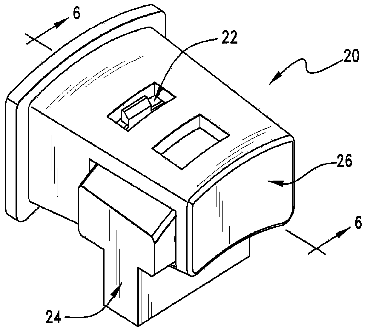
[0027] As shown, a power connector 20 includes a pair of connectors 22 , 24 mated together via an insulating housing 26 . The connectors 22, 24 can be used to transmit power or signals as desired. A number of features on connector 22 are configur...


PUM


Abstract

A connector system includes a first connector with a housing. The housing supports a terminal with an aperture that is positioned adjacent a pocket. A ball is positioned in the pocket and is restrained by the terminal but is configured to partially extend through the aperture. A second connector includes a contact and a magnet attraction member. In operation, when the first and second connector are in a mated position, the ball is urged toward the magnetic attraction member due to a magnetic force and partially extends through the aperture so as to engage the contact, electrically connecting the terminal and the contact.

Description

[0001] References to related applications [0002] This application claims priority to US Provisional Patent Application 61 / 486094, filed May 13, 2010, which is hereby incorporated by reference in its entirety. technical field [0003] The present application relates to an electrical connector, and more particularly relates to a connector suitable for applications requiring higher mating times. Background technique [0004] Connectors are typically configured for low mating cycle applications. For example, many input / output (IO) connectors are expected to accept relatively low mating cycles. However, some applications require significantly more mating cycles. Portable electronic devices, such as laptops and mobile phones for example, can be plugged and unplugged many times a day due to their power requirements. Likewise, medical devices may need to be plugged and unplugged at least once a day, if not more. Over a two- or three-year cycle, this could subject a connector t...

Claims


Application Information

Patent Timeline
IPC IPC(8): H01R11/30H01R13/46
CPCH01R13/6205H01R11/30H01R13/04H01R13/6271
Inventor 罗纳德·C·霍奇维克托·萨德雷约瑟夫·D·科墨西
Owner MOLEX INC
Features
  • R&D
  • Intellectual Property
  • Life Sciences
  • Materials
  • Tech Scout
  • Unparalleled Data Quality
  • Higher Quality Content
  • 60% Fewer Hallucinations
Learn More