

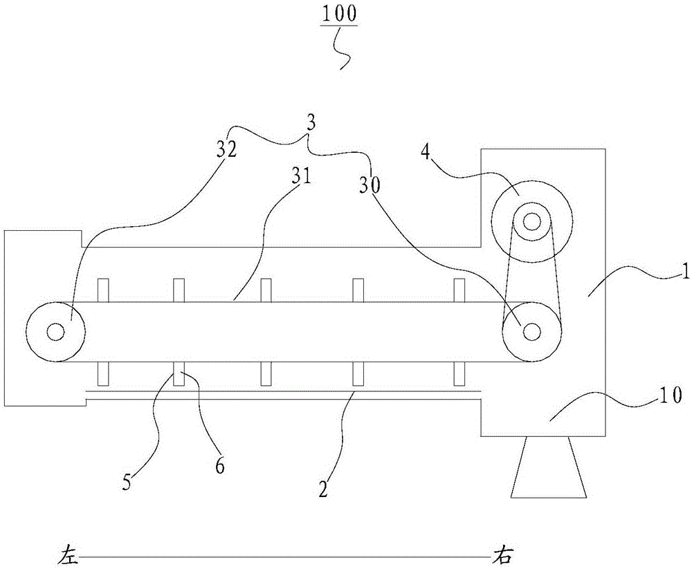
Discharging device for treating waste tire pyrolysis solid products in regenerative pyrolysis furnace
A technology for regenerative pyrolysis furnaces and solid products, applied in incinerators, lighting and heating equipment, combustion methods, etc., can solve the problem of affecting the continuity of production, affecting the normal discharge of the discharge screw, and the screw of the discharge screw device Problems such as jamming, to avoid incomplete discharge and material leakage, reduce follow-up processing costs, and avoid potential safety hazards
- Summary
- Abstract
- Description
- Claims
- Application Information
AI Technical Summary
Problems solved by technology
Method used
Image

Examples
Embodiment Construction
[0022] The embodiments of the present invention are described in detail below. Examples of the embodiments are shown in the accompanying drawings, in which the same or similar reference numerals indicate the same or similar elements or elements with the same or similar functions. The embodiments described below with reference to the drawings are exemplary, and are only used to explain the present invention, but should not be understood as limiting the present invention.
[0023] In the description of the present invention, it should be understood that the terms "center", "longitudinal", "transverse", "upper", "lower", "front", "rear", "left", "right", " The orientation or positional relationship indicated by "vertical", "horizontal", "top", "bottom", "inner", "outer", etc. are based on the orientation or positional relationship shown in the drawings, and are only for the convenience of describing the present invention and simplifying The description does not indicate or imply tha...
PUM
 Abstract
Description
Claims
Application Information