Supercharge Your Innovation With Domain-Expert AI Agents!

a heat exchanger

A heat exchanger, the technology on the other side, applied in the field of heat exchange equipment, can solve the problem that the heat exchanger cannot be disassembled

Inactive Publication Date: 2016-06-01
WUXI JIALONG HEAT EXCHANGER
View PDF4 Cites 0 Cited by
  • Summary
  • Abstract
  • Description
  • Claims
  • Application Information

AI Technical Summary

Problems solved by technology

[0003] The purpose of the present invention is to provide a heat exchanger to solve the problem that the traditional heat exchanger cannot be disassembled

Method used


Image

  • a heat exchanger

Examples


Embodiment Construction

[0018] The present invention will be further described in detail below in conjunction with the accompanying drawings and embodiments. It should be understood that the specific embodiments described here are only used to explain the present invention, but not to limit the present invention. In addition, it should be noted that, for the convenience of description, only some structures related to the present invention are shown in the drawings but not all structures.

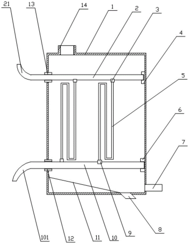
[0019] combine figure 1 The heat exchanger of the present invention will be described in detail.

[0020] The heat exchanger of the present invention includes a shell 1, and also includes an inlet pipe 2, a first connecting piece 3, a first mounting seat 4, a flow guide pipe 5, a second mounting seat 6; a second connecting piece 9, an outlet pipe 10. The second support member 12 and the first support member 13; the first support member 13 is penetrated in the side wall of the housing 1, and the first mount 4 is p...


PUM


Abstract

The invention relates to the technical field of heat exchange equipment, in particular to a heat exchanger. The heat exchanger comprises a shell, a flow inlet pipe, a first connecting part, a first mounting base, a flow guide pipe, a second mounting base, a second connecting part, a flow outlet pipe, a second supporting part and a first supporting part. The first supporting part penetrates through the side wall of the shell, the first mounting base is arranged on the side wall of the other side of the shell, the flow inlet pipe penetrates through the first supporting part, the second supporting part penetrates through the side wall of one side of the shell, the second mounting base is arranged on the side wall of the other side of the shell, and the flow outlet pipe penetrates through the second supporting part. The upper end of the flow guide pipe is connected with the first connecting part, and the lower end of the flow guide pipe is connected with the second connecting part. The flow guide pipe which breaks down can be demounted after the first connecting part and the second connecting part are loosened.

Description

technical field [0001] The invention relates to the technical field of heat exchange equipment, in particular to a heat exchanger. Background technique [0002] Floating coil heat exchanger is a common heat exchange equipment, which is widely used in heating, hot water bathing, petrochemical and other fields for heat exchange. In the prior art, the floating coils in the floating coil heat exchangers are usually welded to form an integral structure, which cannot be disassembled. After the heat exchanger leaves the factory, the heat exchange area of ​​the coils is a fixed value and cannot be adjusted; When the coil is damaged and leaks, the coil can only be blocked and the heat exchange area of ​​the coil is sacrificed. Therefore, the heat exchange area is reduced and the maintenance operation is difficult. Contents of the invention [0003] The purpose of the present invention is to provide a heat exchanger to solve the problem that the traditional heat exchanger cannot be...

Claims


Application Information

Patent Timeline
Patent Type & Authority Patents(China)
IPC IPC(8): F28D7/04F28F9/26
Inventor 鲁涤平
Owner WUXI JIALONG HEAT EXCHANGER
Features
  • R&D
  • Intellectual Property
  • Life Sciences
  • Materials
  • Tech Scout
  • Unparalleled Data Quality
  • Higher Quality Content
  • 60% Fewer Hallucinations
Learn More