Glare shield equipped with emergency vision apparatus
A technology of visual devices and visors, which is used in aircraft indicating devices, optics, emergency equipment, etc.
Inactive Publication Date: 2014-04-02
貝蒂爾 R L 偉杰菲爾特 +2
8 Cites 1 Cited by
AI-Extracted Technical Summary
Problems solved by technology
Stores in compartment when first en...
Method used
[0018] FIG. 1 shows an emergency vision device 2 integrated into a dashboard as an embodiment according to the present invention. The device 2 is applied to an operator station 4, such as an aircraft cockpit, so that the operator can see information sources, such as flight instruments, through the smoke in an emergency event of smoke. In the context of an aircraft cockpit, the operator station 4 includes a windshield 6 and a visor 8 . Apparatus 2 includes an inflatable enclosure 10 having a transparent member 12 and another transparent member 14 that allows an operator 16 to see through the enclosure 10 and windshield 6 in the event of a smoke emergency. This helps the operator control the aircraft and land it safely. The enclosure 10 also includes another transparent member 18 to facilitate the operator to observe the information on the instrument panel 20 . The device 2 comprises a compartment 22 located within the visor 8 . The location of the compartment 22 near where the enclosure is to be deployed and positioned advantageously provides a space-saving arrangement, as will become apparent hereinafter. The enclosure 10 includes a safety valve (not shown) to prevent excessive inflation of the enclosure - this is prior art.
[0024] It can be seen that setting the device 2 in the visor 8 can effectively shorten the duct length 42 from the fan 34 to the airtight cover 10, because the distance between the device 2 and t...
Abstract
A glare shield equipped with an emergency vision apparatus comprises a glare shield in a cockpit and a compartment recessed into the glare shield. A blower is disposed within the compartment. An inflatable first enclosure made of airtight material and having an expanded form when deployed and a deflated form when not in use is connected to the blower with a tubular air passageway. The first enclosure when in the deflated form is stored within the compartment. First and second clear members are disposed at respective first and second ends of the enclosure to enable a user to see through the first enclosure when expanded and observe a source of information at a distal end of the first enclosure while smoke or other particulate matter is in the environment. A switch operably is associated with the blower to activate the blower and thereby inflate the first enclosure when deployed.
Application Domain
Antiglare equipmentAircraft fire/erosion prevention +2
Technology Topic
EngineeringVisual perception +2
Image
Examples
- Experimental program(1)
Example Embodiment
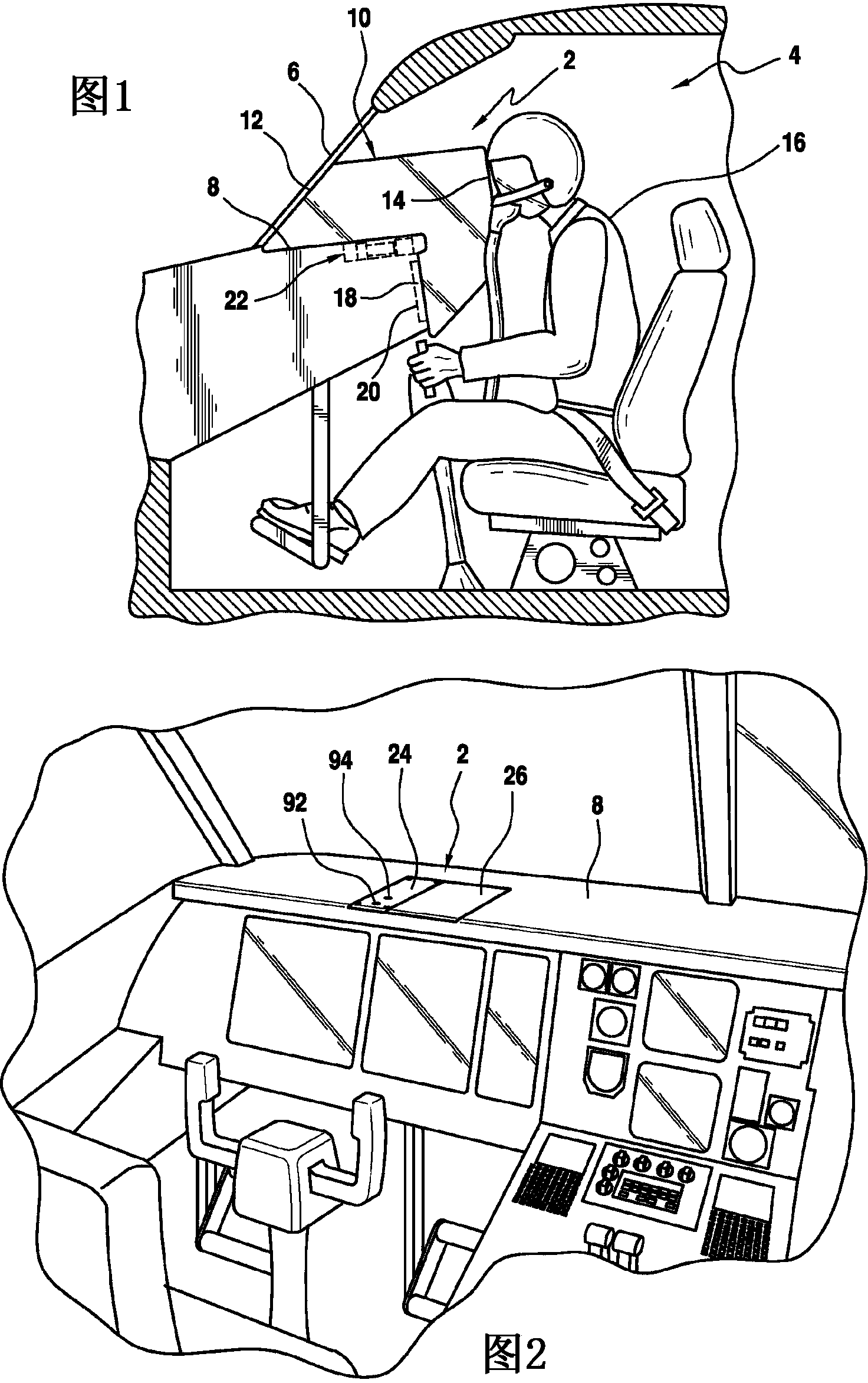
[0018] figure 1 Shown is an emergency vision device 2 integrated into a dashboard as an example according to the invention. The device 2 is applied to an operator station 4, such as an aircraft cockpit, so that the operator can see information sources, such as flight instruments, through the smoke in an emergency event of smoke. In the context of an aircraft cockpit, the operator station 4 includes a windshield 6 and a visor 8 . Apparatus 2 includes an inflatable enclosure 10 having a transparent member 12 and another transparent member 14 that allows an operator 16 to see through the enclosure 10 and windshield 6 in the event of a smoke emergency. This helps the operator control the aircraft and land it safely. The enclosure 10 also includes another transparent member 18 to facilitate the operator to observe the information on the instrument panel 20 . The device 2 comprises a compartment 22 located within the visor 8 . The location of the compartment 22 near where the enclosure is to be deployed and positioned advantageously provides a space-saving arrangement, as will become apparent hereinafter. The enclosure 10 includes a safety valve (not shown) to prevent excessive inflation of the enclosure - this is prior art.
[0019] The airtight cover 10 can be of any shape, as long as there is a clear line of sight between the transparent members 12 and 14 , and between 18 and 14 . Preferably, the orientation and shape of the transparent member 12 should be in close contact with the windshield 6 so as to displace the smoke obstructing the view through the gap between the two. Similarly, member 18 faces and is in intimate contact with instrument panel 20 . Transparent members 12, 14 and 18 should be sufficiently resilient to conform to and seal irregular surfaces with which they come into contact, thereby displacing smoke on such surfaces.
[0020] The enclosure 10 is made of airtight fabric or other elastically pleatable material, such as plastic sheeting. The transparent members 12, 14 and 18 are composed of a pleatable sheet of plastic.
[0021] according to figure 2 As shown, the device 2 is embedded in the visor 8 . The access covers 24 and 26 are visible from outside the visor. The access cover 26 can be easily removed without any tools. The access cover 26 can be secured by standard means, such as magnetic retainers, which provide adequate retention during take-off and landing, and allow the operator to easily and quickly deploy the device 2 in the event of a smoke emergency. to remove it. Preferably, the access covers 24 and 26 are flush with the outer surface of the visor 8 .
[0022] In the normal environment of an operator station, compartment 22 would be installed as part of the instrument panel adjacent to the instrumentation, where it is critical for the operator to be able to see the source of information on the instrumentation in the event of a smoke or visually obstructing emergency of. Preferably, the compartment mounts recessed into the dashboard, with the access covers 24 and 26 aligned with or protruding from the dashboard surface. Compartment 22 may also be mounted to the dashboard surface.
[0023] like image 3 As shown, the access cover 24 can be fixed in a secure position by screws 27 or other standard means. The compartment 22 is divided by a partition wall 29 into a part 28 for housing a fan 34 driven by a motor 34 powered by a set of batteries 38 and a part 30 for housing the enclosure 10 . Before the particulate matter in the ambient air enters the enclosure 10 through the elastic conduit 42 , the filter cartridge 40 filters out the particulate matter. As shown, air flows into the enclosure 10 through the perforated wall portion 44 of the compartment 22 in the direction of arrow 46 . Access to various components inside section 28 is accessible through access cover 24 .
[0024] It can be seen that disposing the device 2 inside the visor 8 can effectively shorten the duct length 42 from the fan 34 to the enclosure 10 because the device 2 is very close to the location where the enclosure 10 will be deployed. This reduces the space required for the storage device 2 . Compartment 22 is also more compact due to the reduced space requirements, as fewer conduits need to be stored, and also reduces weight, which is a very important consideration in an aircraft.
[0025] The switch 48 cooperates with a removable member 50 which maintains the switch 48 in the off state when the member 50 is normally placed within the switch chamber. When the member 50 is moved out, the switch 48 is automatically switched to the closed state, and the motor 36 is started to rotate the fan 34 . The member 50 is connected to the enclosure 10 by conventional means, such as a wire 51, whereby, when the enclosure 10 is removed from the compartment 22, the removable member 50 can be removed together without further action by the operator, therefore, can be automatically Switch 48 is activated. The enclosure 10 is shown in an uninflated state when stored in the compartment 22 .
[0026] Conduit 42 is elastic and malleable such that when enclosure 10 is removed from compartment 22, conduit 42 will extend to a desired length. For storage, conduit 42 is collapsed to a short, compact length, advantageously saving space for compartment 22 . Conduit 42 may consist of a coiled spring wrapped in an airtight fabric, the length of which may be compressed to a shorter length for storage and expanded for deployment. Conduit 42 may also be constructed of a plastic material in which the conduit walls are pleatable or accordion-folded so that it can be extended in length when in use and compressed to a minimum length when in storage. Other known extendable catheter configurations are within the purview of those skilled in the art.
[0027] according to Figure 4 As shown, the removable member 50 is connected to the access cover 26 , and when the access cover 26 is removed, the removable member 50 is also removed, thereby automatically actuating the switch 48 . Member 50 is connected to access cover 26 in a conventional manner, such as wire 51 .
[0028] according to Figure 5 , shows the removable access cover 26 being removed. The removable member 50 is shown coupled to the access cover 26 . from Image 6 It can be seen that the conduit 42 begins to extend when the enclosure 10 is moved out of the compartment portion 30 .
[0029] Figure 7 Shown is a schematic view of the inflatable enclosure 10 being inflated by the fan 34 . The transparent member 12 can be seen in the figure. Positioning the enclosure 10 near or above the compartment 22 is beneficial so that the length of the conduit 42 is minimized, a smaller length of conduit equating to less storage space and weight.
[0030] Also provided on the enclosure 10 is a conduit connector 52 with a removable cover which can be connected to an auxiliary removable hand-held enclosure 54 via a conduit 56, such as Figure 8 shown. The hand-held enclosure 54 also includes transparent members 58 and 60 so that the operator can place it on a portion of the instrument panel within the range of motion of the conduit 56 so that the operator can see through the transparent members 58 and 60 when smoke occurs in the cockpit. See information. The hand straps 61 allow the operator to pass his arm through one of the hand straps, and then grasp the other hand strap with his hand, thereby allowing the user to point and position the hand-held enclosure 54 as desired, such as pointing to the aircraft management system display or electronic device on the console. flight bag. The hand-held enclosure 54 is made of airtight fabric or other foldable and malleable sheet material.
[0031] Figure 9 and Figure 10Shown is another embodiment of the present invention in which the inflatable enclosure 10 is not stored in the compartment 22, which is separate from the compartment 22, but is stored in a bag 62 within the operator's reach. In this embodiment, compartment 22 stores only fan 34, motor 36, battery 38 and filter cartridge 40, saving space for mounting the device on the visor. The conduit 42 is not connected to the enclosure 10 but only communicates into the outlet 64 . The outlet 64 is accessible from outside the compartment 30 . The outlet 64 includes a removable cover 66 which is connected to the removable member 50 via a wire 81 so that when the cover 66 is removed, the removable member 50 is also removed from the switch 48 , thereby activating the fan 34 . Additional outlets 68 and 70 may also be provided remote from the compartment, each having a corresponding removable cover cooperating with removable member 50, if desired. Outlets 68 and 70 may be used for example as enclosure 60 (see Figure 8 ) to inflate with a hand-held assisted inflatable enclosure. The removability of these covers is effective for turning the switch 50 to the ON state position, thereby effectively activating the fan 34 . While the outlet shown leads to the visor surface, it could also lead to other locations, such as outlet 67, to the fascia wall panel. The access cover 65 is used for maintenance purposes.
[0032] When the space inside the visor is limited, Figure 9 The illustrated embodiment is advantageous. Rather than storing the enclosure 10 in the compartment 22, keeping it separate from the compartment 22, such as in a bag 62, the size of the compartment 22 can be reduced.
[0033] according to Figure 11 Fan 34 is operatively connected to resilient conduits 69 , 71 and 73 as shown. The outlets 64, 68 and 70 are provided with respective removable covers 75, 66 and 79, respectively. Each cover may be linked to the removable member 50, such as by a respective wire 81 connected to the member 50, so that when one of the covers is removed and the wire 81 is connected to the cover, the member 50 is effectively removed, The fan 34 is thus activated.
[0034] according to Figure 12 As shown, switch 48 can also be replaced by independent switches 86, 88 and 90, the independent switches are located near the respective covers 79, 75 and 66, wherein the movement of any one cover can effectively open the associated switch, such as using proximity switches . The normally closed main switch 92 can be used to turn off the fan motor 36 when the device 2 is no longer needed after the emergency requiring deployment is over. The bypass switch, normally in the off state, is available when any one of switches 86, 88 and 90 fails. Turning switch 94 to the ON state activates fan motor 36 . Switches 92 and 94 can be toggle keys or push button switches such as figure 2 and image 3 Accessible outside compartment 22 as shown.
[0035] Other ways known by those skilled in the art to replace the switch 48 and the removable member 50 , or the ways of starting the fan motor 36 with the switches 86 , 88 and 90 all fall within the protection scope of the present technology.
[0036] re-reference Figure 9 , the shown covers 66, 75 and 79 are aligned with the upper surface of the visor 8.
[0037] Figure 13 A schematic top view of a simplified compartment 96 is shown. Compartment 96 stores fan 34 , motor 36 and battery 38 . As can be seen from the figure, the compartment 36 has been reduced in size by removing the portion 30 where the enclosure 10 is stored. Since the conduits 69 and 73 are only used to inflate the auxiliary enclosure, they can be removed as required due to space constraints.
[0038] according to Figure 14 As shown, the enclosure 10 has been removed from the bag 62 . An elastic conduit 98 already connected to the enclosure 10 leads to the outlet 64 after the cover 64 is removed. Removal of the cover 66 causes the wire 81 connected to the cover to move the member 50 , thereby triggering the switch 48 . As disclosed above, other means of activating the fan motor 36 can also be used here.
[0039] As can be seen from the above description, the device 2 allows the operator to see gauges or other sources of visual data after a visually obstructive event such as smoke and/or particulate matter from a fire has entered the operator's operating environment. In particular, device 2 enables a clear view out of the windshield and instrument panel in the cockpit of the aircraft, thus allowing the pilot to see important information to guide the aircraft to a safe landing should smoke or other visual obstructions enter the cockpit area .
[0040] Although the device 2 described herein is applied to an aircraft cockpit, the invention can also be applied in other similar environments where an operator at the operator station needs to see, for example, an instrument panel environment of the source information. Such as submarine control stations, nuclear power plant control rooms, oil rigs, or other critical or military environments that require the operator to continue operating in a visually obstructed environment, such as when smoke or other particulate matter enters the operator station and blocks the operator from communicating with the operator. Sight situation of the control panel. Therefore, where gauges, control panels, or important sources of information are located at the operator's station, the operator must be able to see that information when the operator's station encounters a visual obstacle.
[0041] What is described here is the preferred design of the present invention. Further modification, application, and/or combination of the principles of the present invention with known or conventional technologies in the field not disclosed herein can be applied to the technical features, and all belong to the present invention. or the scope of protection of the claims.
PUM


Description & Claims & Application Information
We can also present the details of the Description, Claims and Application information to help users get a comprehensive understanding of the technical details of the patent, such as background art, summary of invention, brief description of drawings, description of embodiments, and other original content. On the other hand, users can also determine the specific scope of protection of the technology through the list of claims; as well as understand the changes in the life cycle of the technology with the presentation of the patent timeline. Login to view more.