
Support used for medical waste liquid collecting system
A waste liquid collection and collection tube technology, applied in the field of supports, can solve the problems of complex structure, decreased material service life, poor appearance, etc., and achieve the effect of simple and compact structure and beautiful appearance.
- Summary
- Abstract
- Description
- Claims
- Application Information
AI Technical Summary
Problems solved by technology
Method used
Image

Examples
Embodiment Construction
[0015] The present invention will be further described below in conjunction with the accompanying drawings.
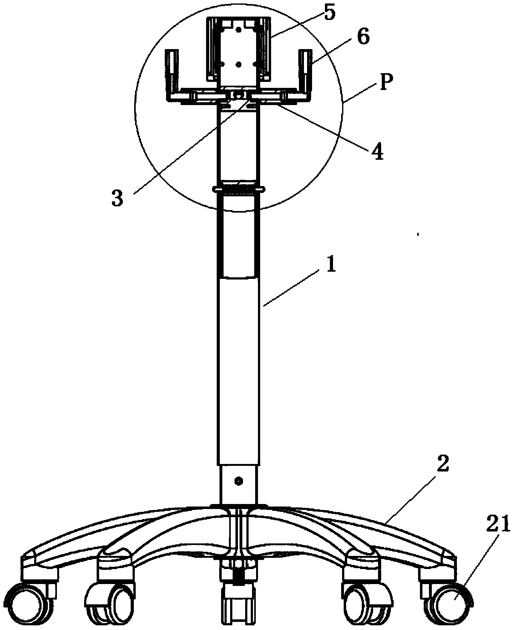
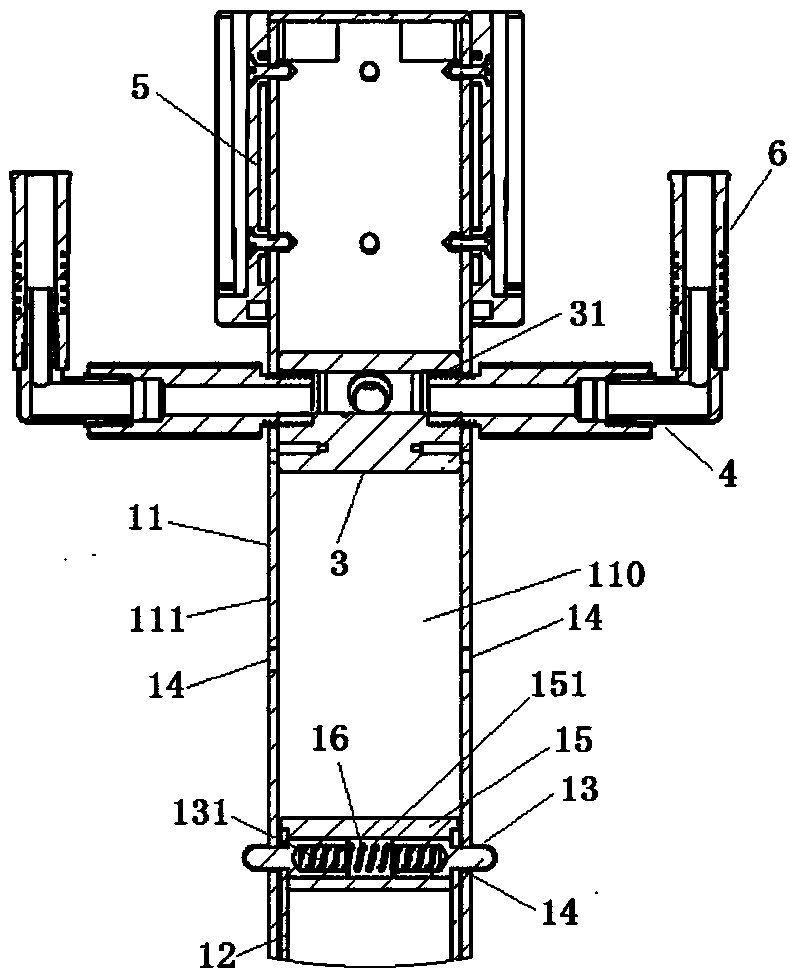
[0016] Please refer to figure 1 and figure 2 . A bracket for a medical waste liquid collection system according to an embodiment of the present invention includes a column 1, a base 2, (N+1) connectors 3, and N branch pipes corresponding to the N collection cylinders of the medical waste liquid collection system 4 and the collection cylinder fixing device 5, wherein, N≥2.
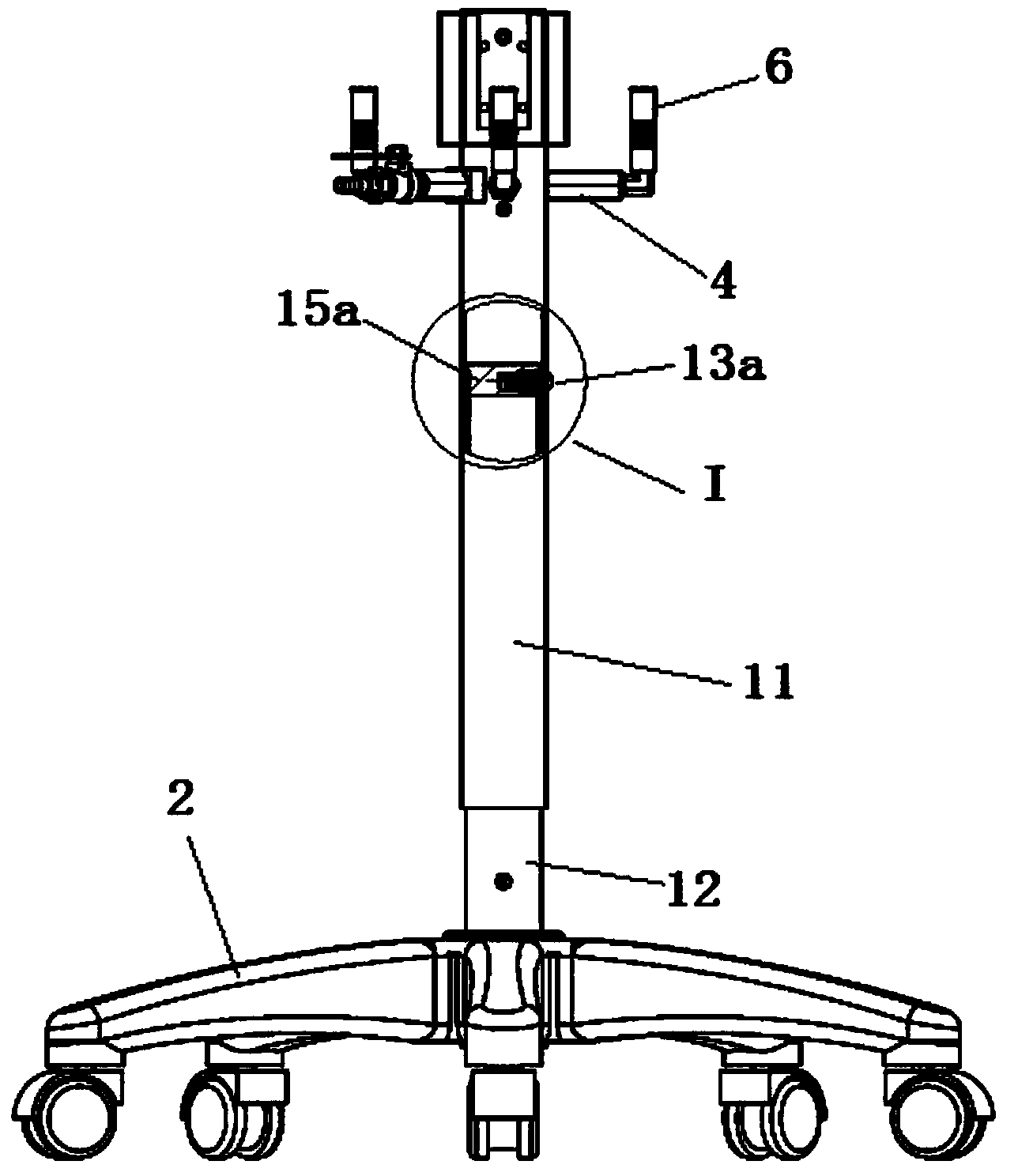
[0017] The upright 1 includes an outer tube 11 and an inner rod 12 . The (N+1) joint 3 is located in the lumen 110 of the outer tube 11 . The upper part of the inner rod 12 is inserted into the lumen 110 of the outer tube 11 , and the lower part of the inner rod 12 is fixed on the base 2 . The inner rod 12 can be a hollow tube or a solid rod. One end of the N branch pipes 4 passes through the pipe wall 111 of the outer pipe 11, and communicates with the N interfaces 31 of the (N+1) joints 3 i...
PUM
 Abstract
Description
Claims
Application Information