Hydraulic ejecting, pushing and sliding installation method for transformer

An installation method and transformer technology, applied in the direction of transformer/reactor installation/support/suspension, inductance/transformer/magnet manufacturing, electrical components, etc., can solve the problems of high lifting command requirements, achieve simple laying, save mechanical costs, The effect of convenient operation

Inactive Publication Date: 2014-05-28
SHANGHAI ERSHIYE CONSTR CO LTD
View PDF3 Cites 15 Cited by
  • Summary
  • Abstract
  • Description
  • Claims
  • Application Information

AI Technical Summary

Problems solved by technology

The above methods all need to formulate a detailed hoisting plan, combined with the site environment, and have relatively high requirements for hoisting command

Method used


Image

  • Hydraulic ejecting, pushing and sliding installation method for transformer

Examples


Embodiment Construction

[0029] The present invention is further illustrated below by specific examples.

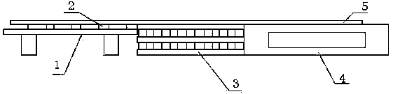
[0030] Such as figure 1 As shown, a hydraulic pushing and sliding installation method of a transformer, which includes steel (wooden) bent frames 2, four hydraulic jacks, two steel rails 5, two hydraulic pushing machines, steel plates, a number of sleepers 3, loaded with transformers Transport vehicle 1, transformer base 4; also include the following steps:

[0031] Step 1. Acceptance of the transformer on site: check that the oil tank is well sealed, that there are no impact marks and deformation on its surface, check that the oil tank cover and flange connecting bolts and sealing plates are complete, and that the fasteners are in good condition; for the transformer that is inflated and transported by the body, observe the transformer The nitrogen inflation pressure of the body (should be 0.01-0.03MPa), check whether the nitrogen replenishment device is reliable. Check the record value with th...


PUM


Abstract

The invention relates to the field of transformer installation, in particular to a hydraulic ejecting, pushing and sliding installation method for a transformer. The hydraulic ejecting, pushing and sliding installation method is characterized by including the steps of firstly, conducting site acceptance on the transformer; secondly, leveling the site; thirdly, conducting initial alignment so that the center line of the transformer can correspond to the center line of a foundation; fourthly, arranging a jack below the transformer; fifthly, jacking up the transformer through the jack; sixthly, erecting a steel or wood framed bent; seventhly, laying two parallel steel rails; eighthly, arranging a hydraulic pushing and sliding machine and adjusting the hydraulic pushing and sliding machine in place; ninthly, enabling the whole transformer to slide; tenthly, detaching the hydraulic pushing and sliding machine, and jacking up the transformer through the jack; eleventhly, removing both the steel rails; twelfthly, installing the transformer, and completing the installation after the transformer is installed in place. Through the steps, auxiliary devices for the transformer can be easily laid, the overall operation is convenient and rapid, and meanwhile mechanical cost and organization cost can be saved.

Description

technical field [0001] The invention relates to the field of transformer installation, in particular to a hydraulic pushing and sliding installation method of a transformer. Background technique [0002] As the core equipment in power supply and distribution facilities, large-scale transformers are precision manufactured, expensive, and have the characteristics of heavy weight, high center of gravity, and large outer dimensions. However, the on-site unloading operation environment is generally more complicated. If the transformer room is in the main factory building, the current common practice is to directly hoist it to the transformer extension track (steel plate) by means of a crane, and then use the traction method to pull it to the position required by the drawing; if the transformer room is outside the main factory building, then Direct hoisting with the help of corresponding truck cranes. The above methods all need to formulate a detailed hoisting plan, combined ...

Claims


Application Information

Patent Timeline
Patent Type & Authority Applications(China)
IPC IPC(8): H01F41/00H01F27/06
Inventor 钱立义郭锋
Owner SHANGHAI ERSHIYE CONSTR CO LTD
Why Eureka
Try Eureka