
Plate cylinder

A printing plate cylinder and printing plate technology, applied in printing, printing plates, printing machines, etc., can solve problems such as inability to achieve precision, and achieve high reproducibility and high precision effects

Inactive Publication Date: 2014-03-19
KOENIG & BAUER AG
View PDF16 Cites 7 Cited by
  • Summary
  • Abstract
  • Description
  • Claims
  • Application Information

AI Technical Summary

Problems solved by technology

This level of precision cannot be achieved with the plate clamping of conventional sheet-fed presses

Method used


Image

  • Plate cylinder
  • Plate cylinder
  • Plate cylinder

Examples


Embodiment Construction

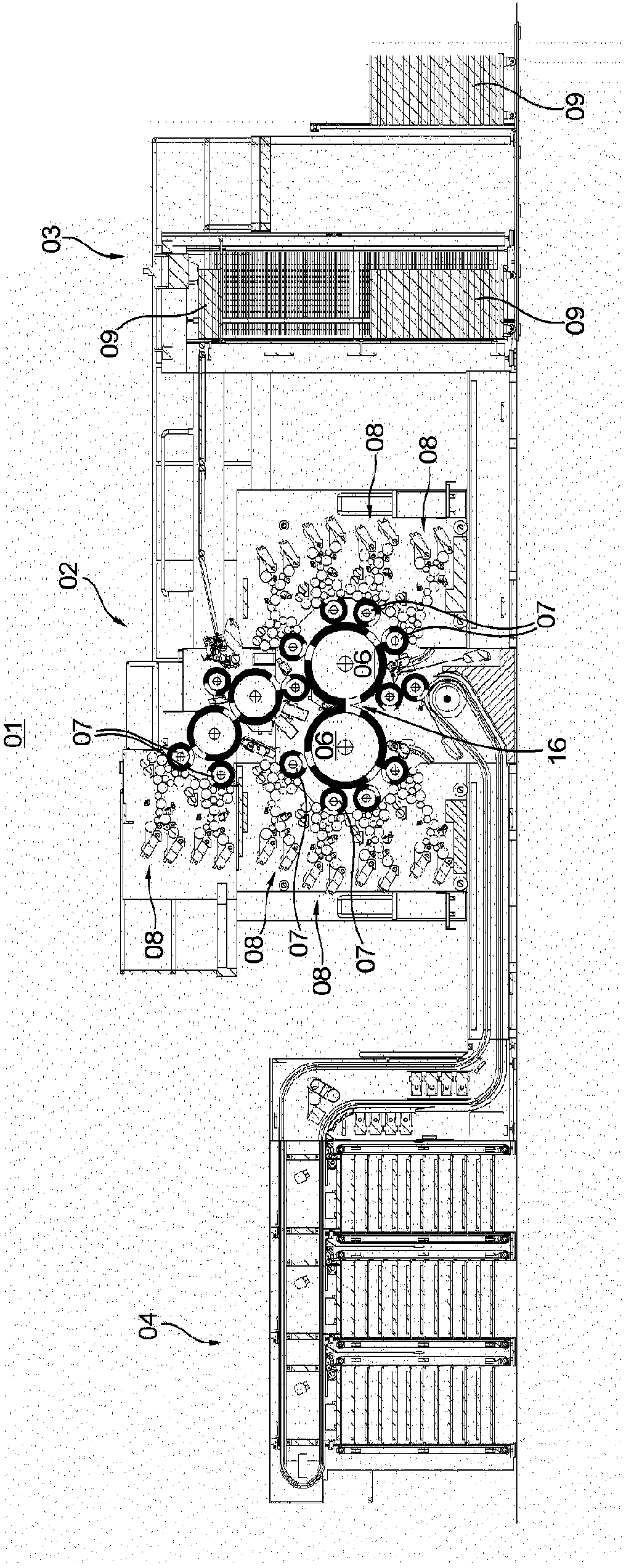
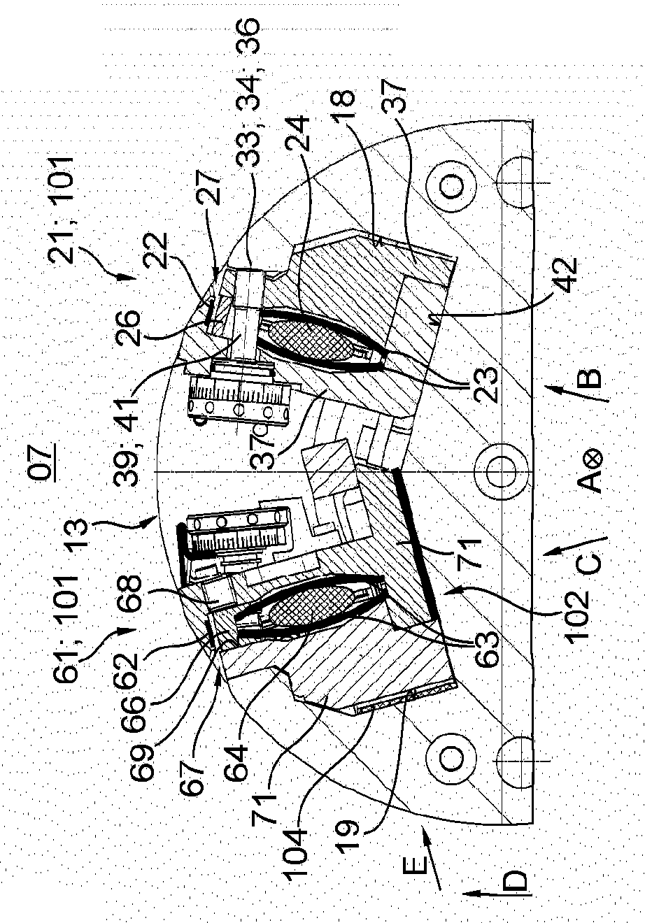
[0047] A printing press 01 designed as a rotary printing press 01 , for example as a sheet-fed rotary printing press 01 , is described below. The printing machine 01 is, for example, the printing machine 01 used for currency printing. The printing press 01 is designed as a printing press 01 for printing a printing material 09 , preferably in sheet-fed form, ie a sheet-fed printing press 01 . The printing press 01 has at least one printing unit 02 with at least one printing unit 08 and at least one inking unit, wherein the at least one printing unit 08 has at least one plate cylinder 07 . The at least one plate cylinder 07 is preferably designed as at least one plate cylinder 07 . Preferably, a plurality of printing units 08 and a plurality of inking units are arranged in the at least one printing unit 02 in order to print different inks on the same printing material 09 in the same production, eg depending on the number of the inking units. In one embodiment, a plurality of p...


PUM


Abstract

The invention relates to a plate cylinder, said plate cylinder having a channel in which a tensioning device is arranged. The tensioning device has a front and a rear clamping device, and the rear clamping device is part of a slide of the tensioning device. The slide is arranged so as to be movable along a tensioning path in a tensioning direction towards the front clamping device within the channel by means of a tensioning drive, and a maximum displacement of the slide in and / or opposite the tensioning direction relative to a plate cylinder body is at least as large as an extension of a provided contact surface between a printing plate that is clamped in the rear clamping device and a radially outer clamping element of the rear clamping device, said extension being measured in the tensioning direction.; The invention also relates to a method for arranging a printing plate onto a plate cylinder.

Description

technical field [0001] The invention relates to a printing plate cylinder according to the preamble of claim 1 and a method for arranging printing plates on a printing plate cylinder according to the features of claim 22 . Background technique [0002] In printing presses, forme cylinders are frequently used which are designed as plate cylinders and which carry printing formes in the form of printing plates. These printing plates can be replaced. For this purpose, a device is required which detachably fixes the printing plate on the plate cylinder. As the demands placed on the accuracy of the printed products produced by the printing press are increasing, so are the demands placed on the accuracy of the arrangement of the printing plates on the plate cylinder. In currency printing, for example, at least the accuracy of the position of the printing plates relative to each other is required to be in the micrometer range. This level of precision cannot be achieved with the p...

Claims


Application Information

Patent Timeline
Patent Type & Authority Applications(China)
IPC IPC(8): B41F27/12
CPCB41F27/1231B41P2227/42
Inventor 帕特里克·克莱斯沃尔克马尔·罗尔夫·施威茨基拉尔夫·哈拉德·索科尔
Owner KOENIG & BAUER AG
Learn More