Linear floor drain and installation method thereof

An installation method and floor drain technology, which is applied in the field of bathroom floor drains, can solve the problems of increased manufacturing costs, low utilization rate of floor drains, water storage, etc., improve stability and reliability, solve universal problems, and simplify installation pipelines Effect

Inactive Publication Date: 2011-06-08
北京中德博力科技有限公司
View PDF5 Cites 8 Cited by
  • Summary
  • Abstract
  • Description
  • Claims
  • Application Information

AI Technical Summary

Problems solved by technology

Due to the frequent use of the floor drain in the shower room, the floor drain water seal can be often replenished, while the floor drain installed on the bathroom floor has a very low usage rate, and the water in the floor drain water seal is easy to dry up after a long period of evaporation. It will become a channel for the odor of the drainage pipe to overflow into the room, polluting the indoor environment
At the same time, the installation of two floor drains leads to complicated pipeline laying in the formation and high installation costs
[0003] In addition, the current structure of the floor drain can only be used for drainage in the same layer or through layers, which has a small scope of application and increases the manufacturing cost.
At the same time, according to the specific installation location, the existing floor drain usually obtains a suitable installation height by cutting the part on the floor drain, such as an adjustable extension cover, which leads to time-consuming and labor-intensive installation, and waste of the cut materials also causes the raw materials for floor drain manufacturing waste of
[0004] In addition, after the floor drain is installed, due to the different materials, it is impossible to make a tight connection between the floor drain and the bathroom floor tiles. When the floor drain is in use, water will flow into the floor drain and the gap between the floor drain and...

Method used


Image

  • Linear floor drain and installation method thereof
  • Linear floor drain and installation method thereof
  • Linear floor drain and installation method thereof

Examples


Embodiment Construction

[0026] The embodiments of the present invention will be described in detail below in conjunction with the drawings.

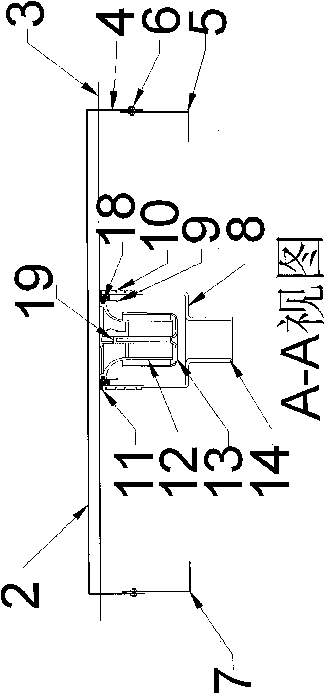
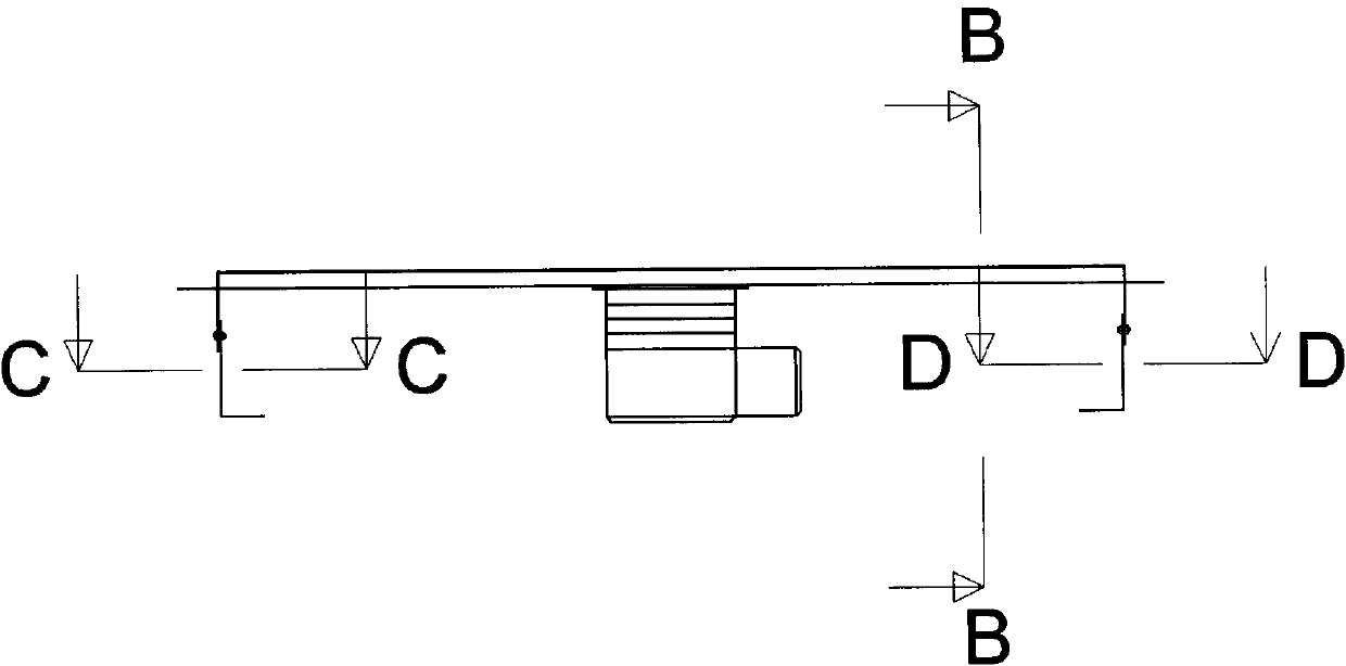
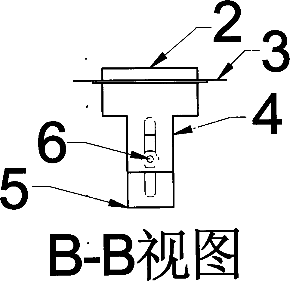
[0027] See attached Figure 1-2 , The floor drain cover 1 is arranged on the floor drain main body 2. The cover is made of metal, such as stainless steel, and is lying in a groove on the top of the floor drain main body 2. The shape of the cover 1 is determined according to its installation position, such as a rectangular strip shape, or a special-shaped structure according to the installation position. However, when the cover 1 is formed in a rectangular strip shape, it can achieve a large drainage floor drain Therefore, it is preferable to use a rectangular strip cover.

[0028] The floor drain main body 2 is made of metal, such as stainless steel, and a waterproof connecting plate 3 is formed integrally with the outer periphery thereof, and the waterproof connecting plate 3 is used to connect with the flexible waterproof cloth 20. The floor drain main body 2 ext...


PUM


Abstract

The invention relates to a linear floor drain which can distinguish dry and wet areas of a washroom and can be interchanged between a same layer and a cross layer according to the application environment, and an installation method thereof. The linear floor drain provided by the invention comprises an elongated cover cap (1), a floor drain main body (2) and a height-adjustable fixed supporting structure, wherein the height-adjustable fixed supporting structure is used for fixedly supporting the floor drain main body (2), the floor drain main body (2) extends downwards so as to form a lower flanging (9), and the outside of the lower flanging (9) is detachably connected with a horizontal water draining adaptor for realizing same-layer water draining or a lower water draining adaptor for realizing cross-layer water draining. Because of adopting the structure above, the linear floor drain solves the problem of generality of floor drains in buildings with different water draining types, avoids the occurrence of dryout phenomenon of water seals, and has the advantage of large water discharge.

Description

Technical field [0001] The invention relates to a floor drain for toilets, in particular to a floor drain that can distinguish between dry and wet areas in the toilet and can be interchanged between the same floor and through floors according to the use environment and an installation method thereof. Background technique [0002] In a bathroom with a shower room, a floor drain is usually set on the floor of the bathroom, and a floor drain is set in the shower room at the same time. The floor drain in the shower room can often be used to supplement the floor drain seal, and the floor drain set on the bathroom floor has a very low usage rate. The water in the floor drain seal will easily dry up after a long time of evaporation. It will become a channel for the odor of the drainage pipe to overflow into the room, polluting the indoor environment. At the same time, the installation of two floor drains leads to complicated pipeline laying in the ground and high installation costs. [...

Claims


Application Information

Patent Timeline
IPC IPC(8): E03F5/04E03C1/122E03C1/28
Inventor 丁璐
Owner 北京中德博力科技有限公司
Why Eureka
Try Eureka