Thermal cooler & dehumidifier for exhalation path in ventilator system

A condenser and gas technology, applied in the field of ventilation system, can solve the problem of increasing the power consumption of the ventilator system

Inactive Publication Date: 2014-06-25
KONINKLJIJKE PHILIPS NV
View PDF6 Cites 7 Cited by
  • Summary
  • Abstract
  • Description
  • Claims
  • Application Information

AI Technical Summary

Problems solved by technology

Additionally, heating the expiratory filter generally increases the power consumption of the ventilator system substantially

Method used


Image

  • Thermal cooler & dehumidifier for exhalation path in ventilator system
  • Thermal cooler & dehumidifier for exhalation path in ventilator system
  • Thermal cooler & dehumidifier for exhalation path in ventilator system

Examples


Embodiment Construction

[0026] The present invention will now be described more fully with reference to the accompanying drawings, in which preferred embodiments of the invention are shown. This invention may, however, be embodied in different forms and should not be construed as limited to the embodiments set forth herein. Furthermore, these embodiments are provided as teaching examples of the invention.

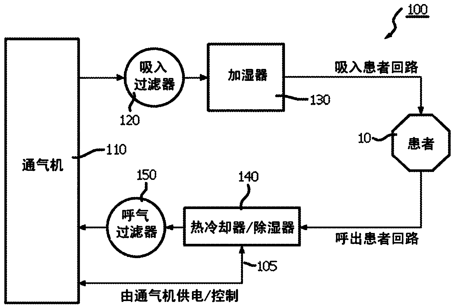
[0027] figure 1 is a functional block diagram of one embodiment of a ventilation device 100 including a condenser in the exhalation path. The ventilation device 100 comprises a ventilator 110 , an inhalation filter 120 , a humidifier 130 , a condenser 140 and an exhalation filter 150 . Apparatus 100 may include a dual-limb patient circuit comprising an inhalation patient circuit, or inspiratory limb, and an exhalation patient circuit, or expiratory limb, both connected to the patient.

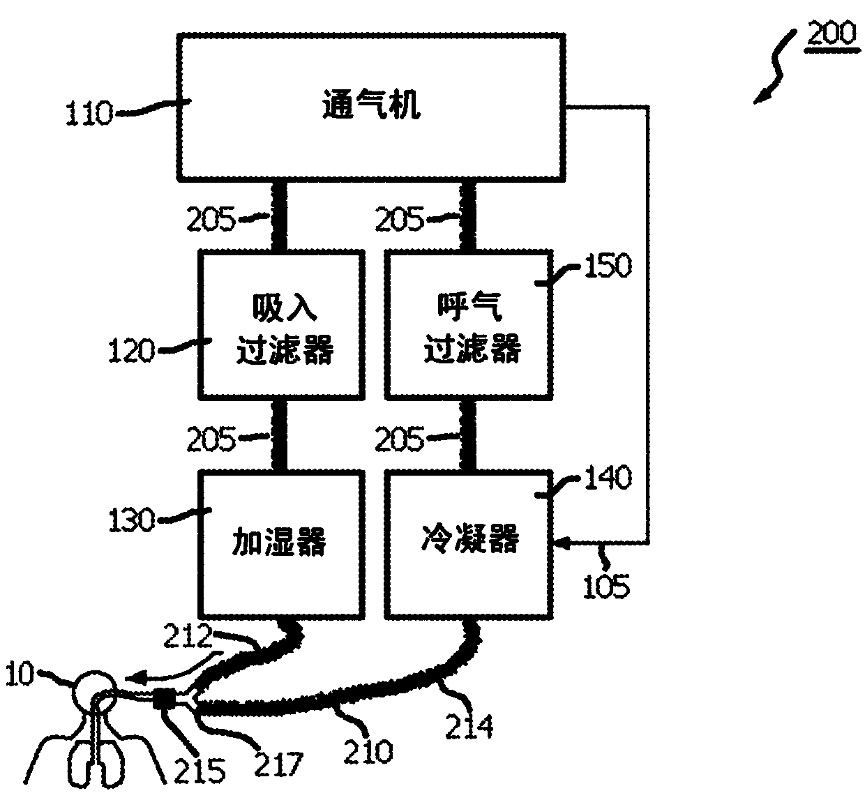
[0028] figure 2 Ventilator system 200 is shown for providing ventilation to patient 10 using elements of ve...


PUM


Abstract

A ventilator system (110) includes: an inhalation filter (120) configured to receive and filter a gas; a humidifier (130) connected to the inhalation filter and configured to adjust a humidity of the filtered gas; a dual-limb patient circuit connected to a patient and configured to supply ventilation to the patient, the dual limb patient circuit including an inspiratory limb connected to the humidifier and configured to supply the filtered gas to the patient and an expiratory limb configured to receive an exhaled gas from the patient; a condenser (140) connected to the expiratory limb, the condenser being configured to cool and remove moisture from the gas from the patient; and an expiratory filter (150) connected to the condenser and configured to filter the cooled gas from the condenser.

Description

field of invention [0001] The present invention relates to patient ventilator systems and devices, and in particular, to a thermal cooler and dehumidifier for the expiratory path of a ventilator system and a ventilation system incorporating such a thermal cooler and dehumidifier. Background technique [0002] Ventilators are used in various settings. For example, in a hospital, patients may be ventilated as part of their medical care. In particular, ventilators are commonly provided in hospital intensive care units (ICUs). [0003] An expiratory filter is a filter for filtering exhaled gas from a patient in the expiratory limb of a dual limb patient circuit used with a ventilator. The purpose of the filter is to reduce cross contamination of the ventilator between patients. For example, the bacterial and viral filtration efficiencies of such exhalation filters are specified according to NIOSH (eg, N100 filters remove 99.97% of particles in exhaled air). [0004] In gener...

Claims


Application Information

Patent Timeline
Patent Type & Authority Applications(China)
IPC IPC(8): A61M16/16A61M16/10A61M16/08
CPCA61M16/0833A61M16/0808A61M2205/0272A61M2205/3606A61M16/0051A61M16/106A61M16/1085A61M16/1065A61M16/16A61M16/0891A61M16/105A61M16/0057A61M16/107A61M16/021
Inventor M·阿希利亚S·加尔德S·艾哈迈德
Owner KONINKLJIJKE PHILIPS NV
Why Eureka
Try Eureka