Chopper circuit

A technology of chopping circuit and busbar, which is applied in the direction of electrical components, adjusting electric variables, instruments, etc., can solve the problems of large stray inductance of chopping circuit, etc., and achieve the effects of improved flexibility, simple circuit layout and easy maintenance

Active Publication Date: 2014-07-09
CRRC YONGJI ELECTRIC CO LTD
View PDF7 Cites 2 Cited by
  • Summary
  • Abstract
  • Description
  • Claims
  • Application Information

AI Technical Summary

Problems solved by technology

[0004] The present invention provides a chopper circuit, which is used to solve the problem of large stray inductance of the chopper circuit in the prior art, realize the reduction of the stray inductance of the circuit, and reduce the generation of peak voltage

Method used


Image

  • Chopper circuit
  • Chopper circuit
  • Chopper circuit

Examples


Embodiment Construction

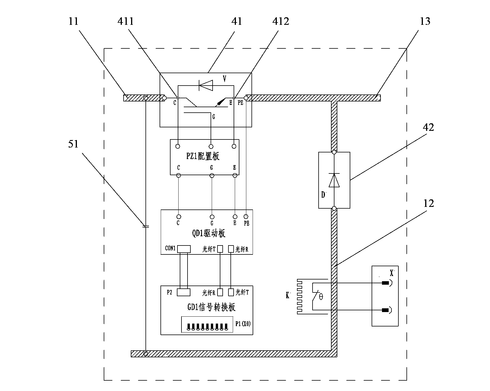
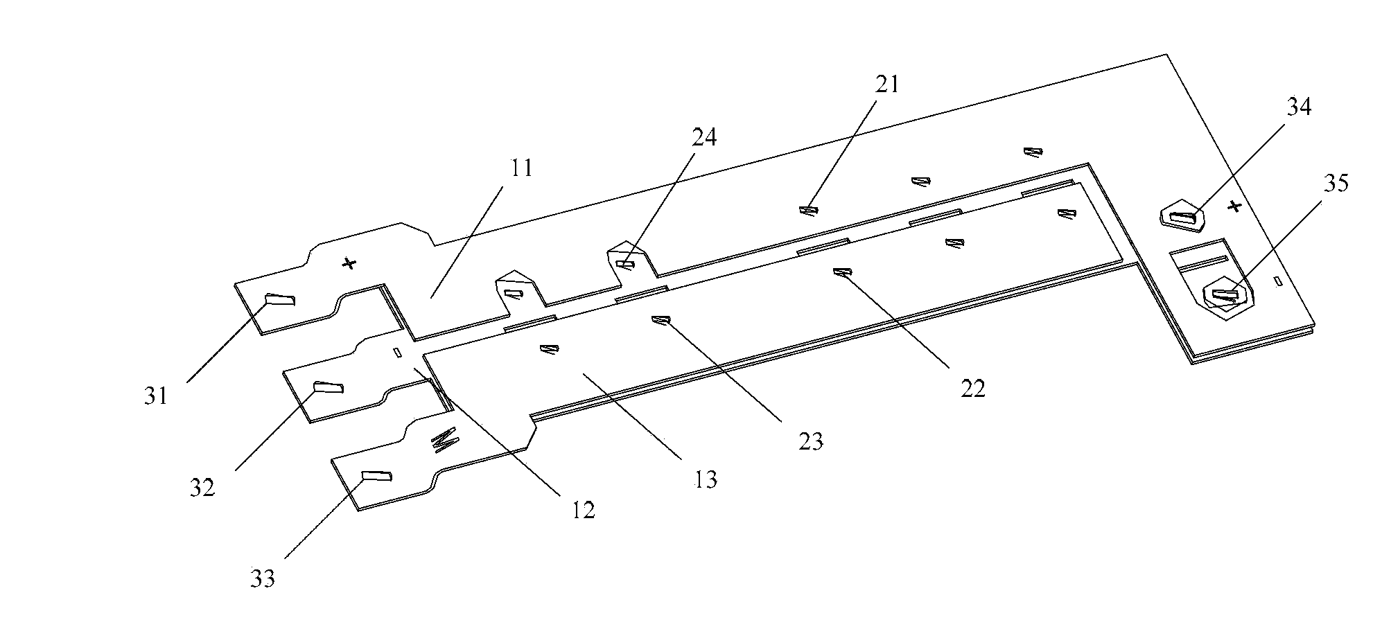
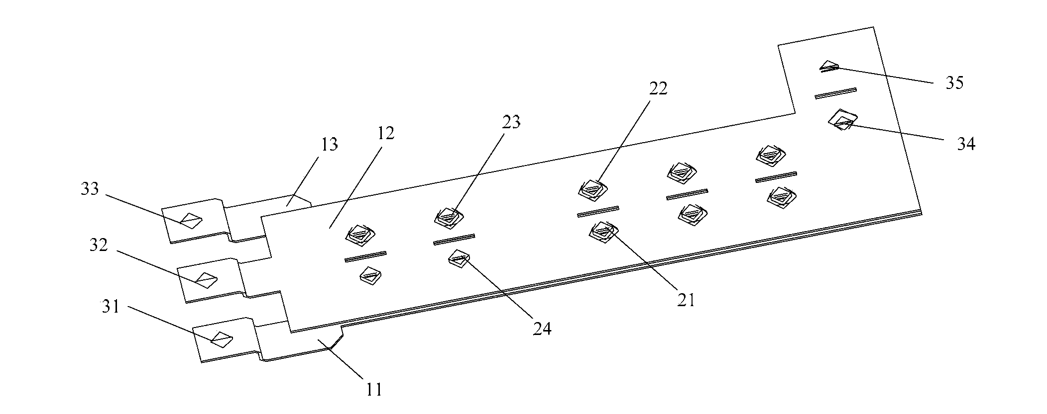
[0019] figure 1 A schematic structural diagram of a chopper circuit provided by an embodiment of the present invention, figure 2 A perspective view of one side of the composite busbar in the chopper circuit provided by the embodiment of the present invention, image 3 A perspective view of the other side of the composite busbar in the chopper circuit provided by the embodiment of the present invention, Figure 4 It is a schematic structural diagram of one side of the composite busbar in the chopper circuit provided by the embodiment of the present invention, Figure 5 for Figure 4 top view of Figure 6 A schematic structural diagram of the other side of the composite busbar in the chopper circuit provided by the embodiment of the present invention. Such as Figure 1-6 As shown, the chopper circuit includes power devices, energy storage devices and composite busbars.

[0020] The composite busbar includes busbars, terminals and connecting parts. The shape of the busbar...


PUM


Abstract

The invention provides a chopper circuit which comprises a power device, an energy storage device and a composite busbar. The composite busbar comprises busbar bodies, terminals and connecting portions, wherein the busbar bodies are in a flat shape, at least two busbar bodies overlap together, the space between every two adjacent busbar bodies is filled with high insulating strength materials so that the two adjacent busbar bodies can be insulated from each other, the terminals are arranged on the busbar bodies and used for being connected with a circuit device, and the connecting portions are arranged on the busbar bodies and used for being connected with a direct-current input end or a chopper output end or the circuit device. The composite busbar at least comprises the first busbar body, the second busbar body and the third busbar body, wherein the first busbar body is connected with a positive electrode of the direct-current input end, the second busbar body is connected with a negative electrode of the direct-current input end, and the third busbar body is connected with the chopper output end. The chopper circuit can reduce stray inductance and spike voltage.

Description

technical field [0001] The invention relates to electrical technology, in particular to a chopper circuit. Background technique [0002] The operating system of an electric locomotive mainly includes traction system and auxiliary system, among which the traction auxiliary converter is an important device to ensure the electric locomotive to achieve electric traction, braking and auxiliary supply, and determines the stability of the high-speed operation of the electric locomotive. [0003] At present, the electrical connection of the key components in the chopper circuit of the traction auxiliary converter, such as the insulated gate bipolar transistor (Insulated Gate Bipolar Transistor, IGBT) and the snubber capacitor, is usually connected by cables or copper bars. In the working state of the traction auxiliary converter, due to the inductance of the IGBT itself and the parasitic inductance on the DC bus connected between the IGBT and the DC energy storage capacitor, the use...

Claims


Application Information

Patent Timeline
Patent Type & Authority Applications(China)
IPC IPC(8): H02M3/155
Inventor 尹梅刘革莉陈宏赵一洁
Owner CRRC YONGJI ELECTRIC CO LTD
Why Eureka
Try Eureka