An ultrasonic flaw detection method, an ultrasonic flaw detection device, and a longitudinal wave shear wave creeping wave integrated ultrasonic oblique probe

A technology of ultrasonic and oblique probes, which is applied to the analysis of solids using sound waves/ultrasonic waves/infrasonic waves, material analysis using sound waves/ultrasonic waves/infrasonic waves, and measuring devices. It can solve problems such as serious intercrystalline reflections and sensitive anisotropic reflections of plates , to achieve the effect of improving flaw detection efficiency, improving accuracy and reducing missed detection rate

Active Publication Date: 2016-08-24
TEWARE
View PDF5 Cites 0 Cited by
  • Summary
  • Abstract
  • Description
  • Claims
  • Application Information

AI Technical Summary

Problems solved by technology

[0013] The present invention aims at the problem that the secondary longitudinal wave and shear wave are difficult to distinguish when the longitudinal wave oblique probe in the prior art is used for flaw detection, and the intergranular reflection is serious when the shear wave oblique probe is used for the flaw detection of coarse-grained welds, and it is sensitive to the anisotropic reflection of the plate. problem, and develop an ultrasonic flaw detection method, ultrasonic flaw detection device and longitudinal wave transverse wave climbing wave integrated ultrasonic angle probe

Method used


Image

  • An ultrasonic flaw detection method, an ultrasonic flaw detection device, and a longitudinal wave shear wave creeping wave integrated ultrasonic oblique probe
  • An ultrasonic flaw detection method, an ultrasonic flaw detection device, and a longitudinal wave shear wave creeping wave integrated ultrasonic oblique probe
  • An ultrasonic flaw detection method, an ultrasonic flaw detection device, and a longitudinal wave shear wave creeping wave integrated ultrasonic oblique probe

Examples


Embodiment Construction

[0069] Such as Figure 19 An ultrasonic flaw detection method shown includes the following steps:

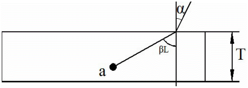
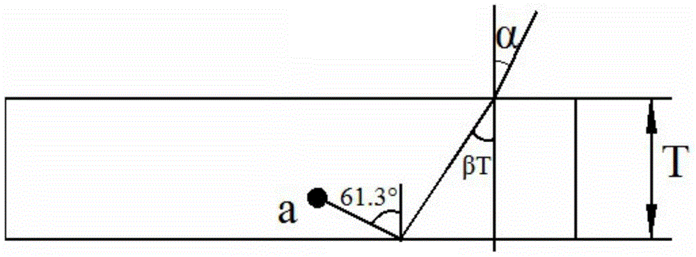
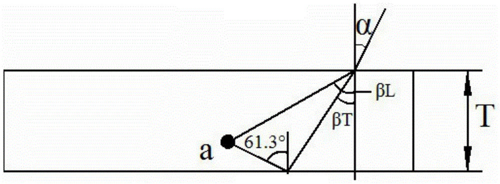
[0070] Step 1: Prepare the ultrasonic oblique probe with the incident angle α, the longitudinal wave refraction angle βL, and the shear wave refraction angle βT. The incident angle α, the longitudinal wave refraction angle βL and the shear wave refraction angle βT pass through the sound velocity of the ultrasonic beam in the first medium , And the sound velocity of longitudinal wave and transverse wave in the second medium, combined with the preset condition that the refraction angle of longitudinal wave and the refraction angle of transverse wave are complementary to each other to determine;

[0071] Step 2: Adjust the ultrasonic oblique probe;

[0072] Step 3: Configure the ultrasonic oblique probe on the outer surface of the workpiece to be inspected;

[0073] Step 4: Send an ultrasonic beam from the ultrasonic oblique probe for flaw detection of the workpiece to be inspected;

[007...


PUM

PropertyMeasurementUnit
viewing angleaaaaaaaaaa

Abstract

The invention discloses an ultrasonic inspection method, an ultrasonic inspection device and an integrated longitudinal wave, transverse wave and creeping wave ultrasonic angle beam probe. The ultrasonic inspection method comprises the following steps: preparing an ultrasonic angle beam probe with an incident angle of alpha, a longitudinal wave refraction angle of betaL and a transverse wave refraction angle of betaT; adjusting the ultrasonic angle beam probe; arranging the ultrasonic angle beam probe on the outer surface of a workpiece to be detected; inspecting the workpiece to be detected by ultrasonic beams emitted from the ultrasonic angle beam probe; and judging whether the workpiece to be detected has defects and corresponding defect positions according to reflection echo received by the ultrasonic angle beam probe. Omni-directional scanning of a steel weld to be detected is realized, a detection leakage rate is reduced, the inspection efficiency is improved, the inspection cost is lowered, the probe traveling distance is reduced by 40 percent compared with that of a transverse wave angle beam probe, and the inspection accuracy can be improved to be over 90 percent.

Description

Technical field [0001] The invention relates to the field of ultrasonic flaw detection, in particular to an ultrasonic flaw detection method, an ultrasonic flaw detection device and an integrated ultrasonic inclined probe of longitudinal wave, transverse wave and creeping wave. Background technique [0002] The ultrasonic oblique probe is a device that realizes the mutual conversion of electric energy and sound energy, and is also a key component for ultrasonic flaw detection. It is mainly composed of piezoelectric wafers and can transmit and receive ultrasonic waves. The ultrasonic oblique probe in the prior art usually includes a transverse wave oblique For probes, longitudinal wave oblique probes and creeping wave oblique probes, the propagation direction and vibration direction of the transverse wave are perpendicular to each other, and the propagation direction and vibration direction of the longitudinal wave are consistent. [0003] The A-type pulse ultrasonic flaw detection ...

Claims


Application Information

Patent Timeline
Patent Type & Authority Patents(China)
IPC IPC(8): G01N29/04G01N29/24
Inventor 曲世发
Owner TEWARE
Why Eureka
Try Eureka