Oil-mist-free energy-saving and low-consumption pusher leg drill

A rock drill and gas consumption technology, which is applied to reciprocating drilling rigs, mechanical equipment, engine components, etc., can solve problems such as vibration, large recoil force, high impact back pressure, and large internal friction, and achieve convenient refueling operations and lubricating oil savings , the effect of structural simplification

Inactive Publication Date: 2014-09-03
罗亮光 +1
View PDF8 Cites 2 Cited by
  • Summary
  • Abstract
  • Description
  • Claims
  • Application Information

AI Technical Summary

Problems solved by technology

Its main problems—vibration and recoil are large, can also be solved through improvement measures; at the same time, through decades of production practice and comparison with similar rock drills at home and abroad, hidden shortcomings of valveless rock drills have also been found : High impact back pressure and large internal friction directly affect the excellent performance of the product
[0004] The traditional lubrication method of the existing air leg rock drills at home and abroad is to use a separate external oiler (commonly known as the oil pot), mix the oil and gas, and distribute it to the internal surfaces of the machine through high-pressure air flow, and most of the gas with mineral oil is treated as Exhaust gas is quickly discharged into the atmosphere, which not only consumes a lot of fuel, but also pollutes the environment and destroys the ecology, and also affects the quality of rock drilling operations, the safety of operators, and the loss of labor protection supplies. Therefore, the majority of mine workers have long been eagerly looking forward to a solution

Method used


Image

  • Oil-mist-free energy-saving and low-consumption pusher leg drill
  • Oil-mist-free energy-saving and low-consumption pusher leg drill
  • Oil-mist-free energy-saving and low-consumption pusher leg drill

Examples


Embodiment Construction

[0060] The present invention will be further described in detail below in conjunction with the accompanying drawings and embodiments.

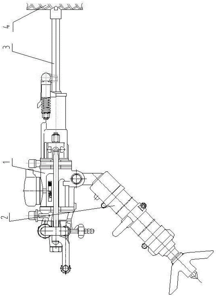
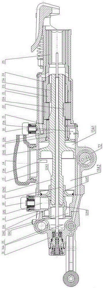
[0061] see figure 1 , The air leg rock drill of the embodiment of the present invention includes a main engine 1, an air leg 2, and a drilling tool 3, and 4 is a rock mass. see figure 2 , the main engine 1 includes a valve body 11 and a handle body 31, a cylinder 13 and a piston 12, a guide body 15 and a guide sleeve 16, a ratchet screw nut 22, a rotating sleeve 24 and a spline sleeve 23, a drill sleeve 25, and a machine head 21. see figure 2 and Figure 13 , Piston 12 is a three-cylinder structure, that is, the front end of the piston is a front striking rod 12A (the right end in the figure is the front), the middle part is a middle large circle 12A1, and the rear end is a rear gas distribution rod 12A2. From figure 2 It can be seen that the front end of the cylinder 13 is fixedly connected with the rear stop of the guide body 15, the...


PUM


Abstract

The invention discloses an oil-mist-free energy-saving and low-consumption pusher leg drill, which has the main technical scheme that a piston is of a three-cylinder structure; support friction pairs are arranged between a beating rod arranged at the front part of the piston and a guide sleeve inner hole, and between a gas distributing rod arranged at the back part of the piston and a valve body inner hole; a gap of the support friction pairs is smaller than a gap between a large circle of the middle part of the piston and a gas cylinder inner hole; the large circle of the middle part of the piston is suspended; a front oil chamber and a back oil chamber are respectively and additionally arranged in vacant positions of a guide body and a valve body and are not mutually communicated; and the dimension of the back end of the gas distributing rod arranged at the back part of the piston meets the requirement that when the piston forwards moves to a state that the back end surface of the large circle of the middle part of the piston is positioned at the back boundary of a gas cylinder exhaust opening, the back end surface of the tail part of the piston lags several millimeters of the back boundary of a valve body return gas inlet. The invention provides the oil-mist-free energy-saving and low-consumption pusher leg drill with the advantages that economization (gas saving) is achieved; the working efficiency is higher; oil-mist-free exhaust can also be realized; good environment-friendly and ecological effects are achieved; in addition, resources are saved; and the structure is more reasonable.

Description

technical field [0001] The invention belongs to the technical field of construction machinery equipment, and in particular relates to an oil-mist-free, energy-saving and low-consumption air-leg rock drill. Background technique [0002] The existing air-leg rock drill is widely used in China due to its stable performance, easy operation and reliable use, and it uses air as the power medium. It is called a "conventional weapon" used in mining and stonework . It is estimated that the current national annual output is nearly 200,000 units (sets). Although this product is not large, it has a large quantity and a wide range, which is directly related to the national economy, the people's livelihood and environmental protection. Among the four models of Guoyou products evaluated by the state, the valveless rock drill (YTP26) is one of them. In the past, most of our understanding stayed on the viewpoint of traditional mechanics, and the understanding and application of modern mech...

Claims


Application Information

Patent Timeline
Patent Type & Authority Applications(China)
IPC IPC(8): E21B1/30F16N7/38
Inventor 罗亮光罗晓晖张立刚曹振来
Owner 罗亮光
Why Eureka
Try Eureka