Input adaptive auto-excitation type Zeta converter
A self-adaptive, converter technology, which is applied in the direction of conversion devices and instruments that convert DC power input into DC power output and output power, to achieve the effect of reducing freewheeling conduction loss and small current detection loss
- Summary
- Abstract
- Description
- Claims
- Application Information
AI Technical Summary
Problems solved by technology
Method used
Image
Examples
Embodiment 1
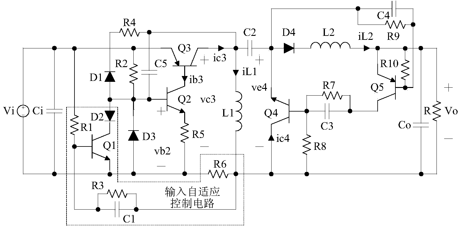
[0034] refer to image 3 , Embodiment 1 includes a main circuit and an input adaptive control circuit for adaptive current limiting protection, the main circuit includes an input capacitor Ci, a PNP type BJT transistor Q3, a capacitor C2, a diode D4, an inductor L1, an inductor L2, an output The capacitor Co, the freewheeling sub-circuit for reducing the freewheeling conduction loss and the driving circuit for driving the PNP type BJT transistor Q3. The drive circuit includes NPN type BJT tube Q2, resistor R2, resistor R4, capacitor C5, resistor R5, diode D3 and diode D1; the input adaptive control circuit includes NPN type BJT tube Q1, diode D2, resistor R1, resistor R3, resistor R6 and capacitor C1; the freewheeling sub-circuit includes a PNP type BJT tube Q5, an NPN type BJT tube Q4, a resistor R7, a resistor R9, a resistor R8, a resistor R10, a capacitor C3 and a capacitor C4. The role of diode D3 and capacitor C5 is to improve the switching speed of NPN type BJT tube Q2,...
Embodiment 2
[0043] refer to Figure 6 , Embodiment 2 On the basis of Embodiment 1, the diode D3 is omitted, and the diode D3 is replaced by a Zener tube Z. The cathode of the Zener tube Z is connected to the base of the NPN type BJT tube Q2, and the anode of the Zener tube Z is connected to the DC The negative terminal of the voltage source Vi is connected, and the voltage regulator tube Z has the function of widening the working range of the circuit.
[0044] refer to Figure 7-Figure 8 , The working principle of the circuit of embodiment 2 is similar to that of embodiment 1, and also has an input adaptive current limiting function. In a steady-state working cycle (t21 to t23), the working state of embodiment 2 in the mode of critical continuous inductor current iL1 and intermittent inductor current iL2 can be roughly divided into two stages: t21 to t22 and t22 to t23. The main difference lies in: when the embodiment 2 is in the period from t21 to t22, the base voltage vb2 of Q2 is equ...
PUM
 Abstract
Description
Claims
Application Information
 - R&D
- Intellectual Property
- Life Sciences
- Materials
- Tech Scout
- Unparalleled Data Quality
- Higher Quality Content
- 60% Fewer Hallucinations
Browse by: Latest US Patents, China's latest patents, Technical Efficacy Thesaurus, Application Domain, Technology Topic, Popular Technical Reports.
© 2025 PatSnap. All rights reserved.Legal|Privacy policy|Modern Slavery Act Transparency Statement|Sitemap|About US| Contact US: help@patsnap.com


