Supercharge Your Innovation With Domain-Expert AI Agents!

Automatic thermal sleeve device and its control method

An automatic and packaged technology, applied in the direction of manufacturing tools, transportation and packaging, conveyor objects, etc., can solve the problems of difficult rotation of hole workpieces, many unsafe factors, high temperature, etc.

Active Publication Date: 2017-09-22
HITACHI ELEVATOR GUANGZHOU
View PDF10 Cites 0 Cited by
  • Summary
  • Abstract
  • Description
  • Claims
  • Application Information

AI Technical Summary

Problems solved by technology

For example, when assembling the rotor assembly of a servo motor, the pulley needs to be installed in the brake pulley using a shrink-fit process. The traditional method is to manually lift the pulley and the brake pulley to the assembly line. When the pulley flows to the heating station, the intermediate frequency The heating coil is lifted by the cylinder and enters the inner hole of the pulley for heating. When the heating time reaches the set value, the heating coil is lowered, and the pulley is manually transported to fit with the brake pulley. The installation holes are aligned with the installation holes on the brake wheel, and finally the bolts are tightened, and the shrink-fit process is completed. This method has the following defects: the temperature of the hole-type workpiece is high after heating, and there are many unsafe factors in the process of manual handling of the set, and the hole After the shaft-type workpiece is inserted into the shaft-type workpiece, the temperature drops rapidly, and the rotation of the hole-type workpiece is difficult when it is aligned with the mounting hole.

Method used


Image

  • Automatic thermal sleeve device and its control method
  • Automatic thermal sleeve device and its control method
  • Automatic thermal sleeve device and its control method

Examples


Embodiment Construction

[0034] Embodiments of the present invention are described in detail below in conjunction with accompanying drawings:

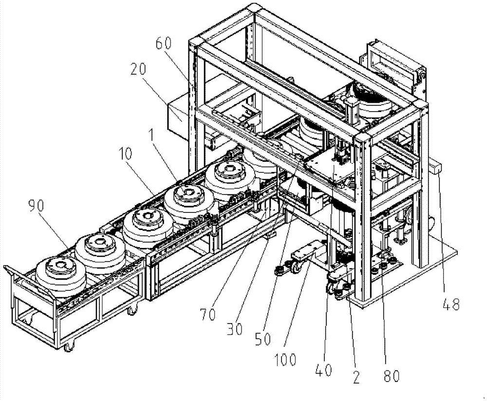
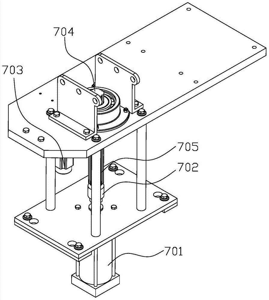
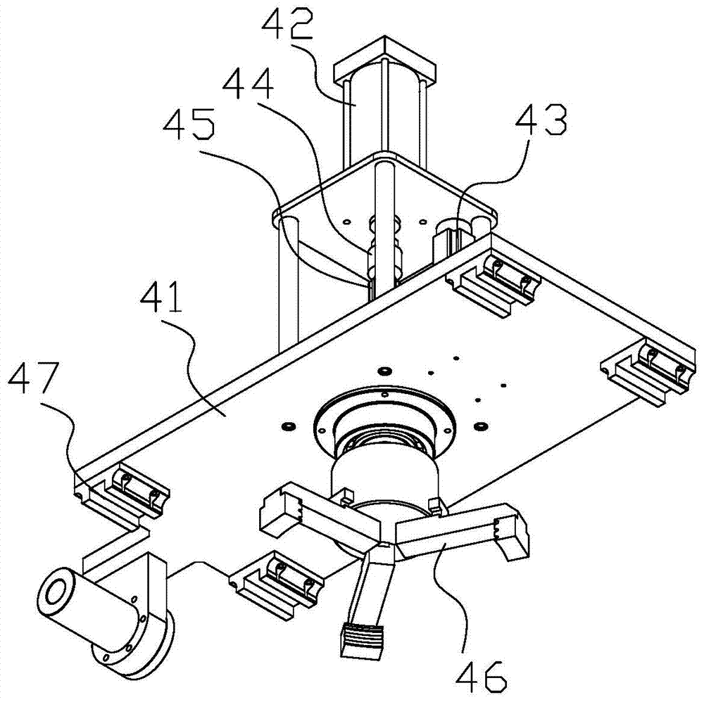
[0035] Such as figure 1 As shown, an automatic shrink-fitting device includes an assembly line 10, a first hole-pairing mechanism 20, a second hole-pairing mechanism 30, a grasping mechanism 40, a heating mechanism 50, and a mounting horizontal frame 60 across the assembly line 10. Said assembly line 10 is provided with a suiting station, said suiting station is provided with a positioning and rotating mechanism 70, said grasping mechanism 40 is movably arranged on said installation horizontal frame 60, and said first pair of hole mechanism 20 It is arranged on the side of the positioning and rotating mechanism 70, the positioning and rotating mechanism 70, the heating mechanism 50, and the second pair of hole mechanism 30 are all arranged below the grasping mechanism 40, and the first pair of hole mechanism 20 has The first detection point, the second hole m...


PUM


Abstract

The invention discloses an automatic hot shrinkage device and a control method of the automatic hot shrinkage device. The automatic hot shrinkage device comprises an assembly line, a first hole alignment mechanism, a second hole alignment mechanism, a grabbing mechanism, a heating mechanism and an installation cross frame. A covering station is arranged on the assembly line, a positioning rotary mechanism is arranged on the covering station, the grabbing mechanism is movably arranged on the installation cross frame, the first hole alignment mechanism is arranged on the side face of the positioning rotary mechanism, the positioning rotary mechanism, the heating mechanism and the second hole alignment mechanism are all arranged below the grabbing mechanism, the first hole alignment mechanism is provided with a first detection point, the second hole alignment mechanism is provided with a second detection point, and the plane formed by a vertical line passing the first detection point and a vertical line passing the second detection point is parallel to a motion trail formed by moving the grabbing mechanism from the portion above the second hole alignment mechanism to the portion above the positioning rotary mechanism. Automatic hole alignment hot shrinkage of shaft workpieces and hole workpieces can be easily achieved, hole alignment is accurate, and labor cost is reduced.

Description

technical field [0001] The invention relates to the technical field of thermal sleeves, in particular to an automatic thermal sleeve device and a control method thereof. Background technique [0002] Shrink-fitting technology is an assembly process for interference fit parts. Using the characteristics of thermal expansion and cold contraction of objects, the hole diameter will naturally become larger after the hole-type workpiece is heated to a certain temperature, so as to facilitate the shaft-type workpiece to fit on it. purpose within. For example, when assembling the rotor assembly of a servo motor, the pulley needs to be installed in the brake pulley using a shrink-fit process. The traditional method is to manually lift the pulley and the brake pulley to the assembly line. When the pulley flows to the heating station, the intermediate frequency The heating coil is lifted by the cylinder and enters the inner hole of the pulley for heating. When the heating time reaches ...

Claims


Application Information

Patent Timeline
Patent Type & Authority Patents(China)
IPC IPC(8): B23P11/02B65G47/90B65G13/11
CPCB23P11/025B65G47/34B65G47/82B65G47/901B65G47/905
Inventor 陈森黄诗成王新
Owner HITACHI ELEVATOR GUANGZHOU
Features
  • R&D
  • Intellectual Property
  • Life Sciences
  • Materials
  • Tech Scout
  • Unparalleled Data Quality
  • Higher Quality Content
  • 60% Fewer Hallucinations
Learn More