Direct-axis magnetic field enhanced type wide-range speed control permanent magnet brushless motor for electric automobile

A permanent magnet brushless motor, electric vehicle technology, applied in the direction of electric vehicles, motors, vehicle components, etc., can solve the problems of difficult adjustment of the air gap magnetic field, narrow speed regulation range, low output power, etc., and achieve increased direct-axis inductance , the effect of wide speed regulation range and high power density

Active Publication Date: 2014-12-31
JIANGSU UNIV
View PDF9 Cites 19 Cited by
  • Summary
  • Abstract
  • Description
  • Claims
  • Application Information

AI Technical Summary

Problems solved by technology

[0007] The purpose of the present invention is to provide a traction permanent magnet brushless motor for electric vehicles with simple structure, greater direct-axis inductance than quadrature-axis inductance, high efficiency, high power density, and wide speed-adjustable operating range, so as to solve the problem of traditional built-in permanent magnet brushless motors. The air gap magnetic field of the brush motor is difficult to adjust, the speed range is narrow, and the output power and efficiency are low at high speed.

Method used


Image

  • Direct-axis magnetic field enhanced type wide-range speed control permanent magnet brushless motor for electric automobile
  • Direct-axis magnetic field enhanced type wide-range speed control permanent magnet brushless motor for electric automobile
  • Direct-axis magnetic field enhanced type wide-range speed control permanent magnet brushless motor for electric automobile

Examples


Embodiment Construction

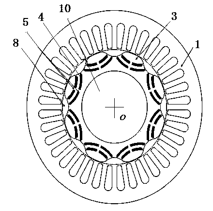
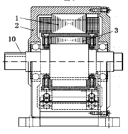
[0031] see figure 1 and figure 2 , the present invention includes a stator 1, a rotor 3, a rotating shaft 10 and an end cover 2, the stator 1 and the end cover 2 are fixedly connected together, the rotor 3 is coaxially located inside the stator 1, the center of the rotor 3 is coaxially connected to the rotating shaft 10, and the rotor 3 The central slot of the shaft is used to place the rotating shaft 10. There is an air gap between the inner wall of the stator 1 and the outer wall of the rotor 3, and the thickness of the air gap is related to the power level of the motor, the selected permanent magnet material, and the processing and assembly process of the stator 1 and rotor 3 . The rotor 2 has a salient pole structure, and the number of teeth of the rotor 2 is equal to the number of poles of the motor. Each tooth portion of the rotor 3 is fixedly inlaid with an arc-shaped permanent magnetic steel 4 . Both the stator 1 and the rotor 3 are formed by laminating silicon ste...


PUM


Abstract

The invention discloses a direct-axis magnetic field enhanced type wide-range speed control permanent magnet brushless motor for an electric automobile. A magnetic barrier fills each slot of a rotor, and the magnetic barriers are symmetrical relative to a centerline, i.e., a quadrature axis, of slot parts of the rotor; four sections of arc-shaped permanent magnet steel are fixedly embedded on each tooth part of the rotor, the four sections of arc-shaped permanent magnet steel are divided into an inner layer and an outer layer, two sections are arranged on each layer, the two sections of permanent magnet steel on each layer are the same in structure and are symmetrical relative to a centerline, i.e., a direct axis of the tooth parts of the rotor, the two sections of permanent magnet steel on the same layer do not run through each other and are not connected with each other, and an arc-shaped magnetic bridge is formed between the two sections of permanent magnet steel; a circle center of each section of permanent magnet steel is located on the diameter of the rotor; the direct-axis inductance of the motor is larger than the quadrature-axis inductance, so that the motor can adopt a control method with zero direct-axis current and can also adopt a direct-axis magnetic field enhanced control method during low-speed operation or startup, and can adopt a coordinated control method of direct-axis magnetic field enhancement and slight direct-axis magnetic field weakening during high-speed operation, and the speed control range is wider.

Description

technical field [0001] The invention relates to a permanent magnet brushless motor, belonging to the field of motor manufacturing and control, in particular to a permanent magnet brushless motor that is suitable for applications such as traction hybrid vehicles and electric vehicles that require wide speed regulation, high efficiency, high power density and other drive performance requirements. Permanent magnet brushless motor. Background technique [0002] As one of the key executive components of hybrid electric vehicles and electric vehicles, the driving performance of the vehicle drive motor directly affects the performance of the whole vehicle of hybrid electric vehicles and electric vehicles. In the field of vehicle drive motors, traditional built-in permanent magnet brushless motors are used, which have the advantages of high efficiency and high power density. Since this type of permanent magnet brushless motor uses permanent magnet steel as a single excitation sourc...

Claims


Application Information

Patent Timeline
Patent Type & Authority Applications(China)
IPC IPC(8): H02K1/27H02K1/24H02K1/16H02K3/28
CPCY02T10/64
Inventor 朱孝勇闫兵全力陈龙屠红娇
Owner JIANGSU UNIV
Why Eureka
Try Eureka