Smart Uniform Pedal Moped

A technology for mopeds and pedals, which is applied to motor vehicles, bicycles, vehicle parts, etc., can solve problems such as acceleration hazards, inconvenient riding, and large resistance, and meets the requirements of simple production technology and processing, and realizes diversified functions. The effect of production costs

Active Publication Date: 2016-07-13
HAIMEN THE YUECAI TEXTILE TECH CO LTD
View PDF4 Cites 0 Cited by
  • Summary
  • Abstract
  • Description
  • Claims
  • Application Information

AI Technical Summary

Problems solved by technology

[0002] At present, the power assist system of electric vehicles on the market is not a real power assist. When the pedal is stepped on, the motor will output a maximum force to the wheel. The magnitude of this force remains unchanged. To change the magnitude of this force, you need It is done through the accelerator; but when the battery is out of power, the boost will also disappear, but when you want to use the pedals to drive the wheels, the resistance at this time will be very large, which is very inconvenient to ride. Walking, the main source of this resistance is the magnetic resistance inside the drive motor on the driving wheel; in fact, when the wheels are driven by the accelerator, the resistance is greater when the wheels are driven by pedals and then accelerated. Because the driving motor is working, the driving force is very large; therefore, the existing electric vehicles have to be designed so that when the pedal is stepped on, the motor will output a maximum force to the wheels, and the magnitude of this force remains unchanged. It is dangerous to suddenly add force and accelerate when using the pedals
However, pedal bicycles need a lot of power to step on the pedals to drive the wheels in natural environments such as wind and uphill, which will be very tiring and hard work over time, which is not conducive to people's health and travel

Method used


Image

  • Smart Uniform Pedal Moped
  • Smart Uniform Pedal Moped
  • Smart Uniform Pedal Moped

Examples


Embodiment Construction

[0023] The present invention will be further described below in conjunction with accompanying drawing and specific embodiment:

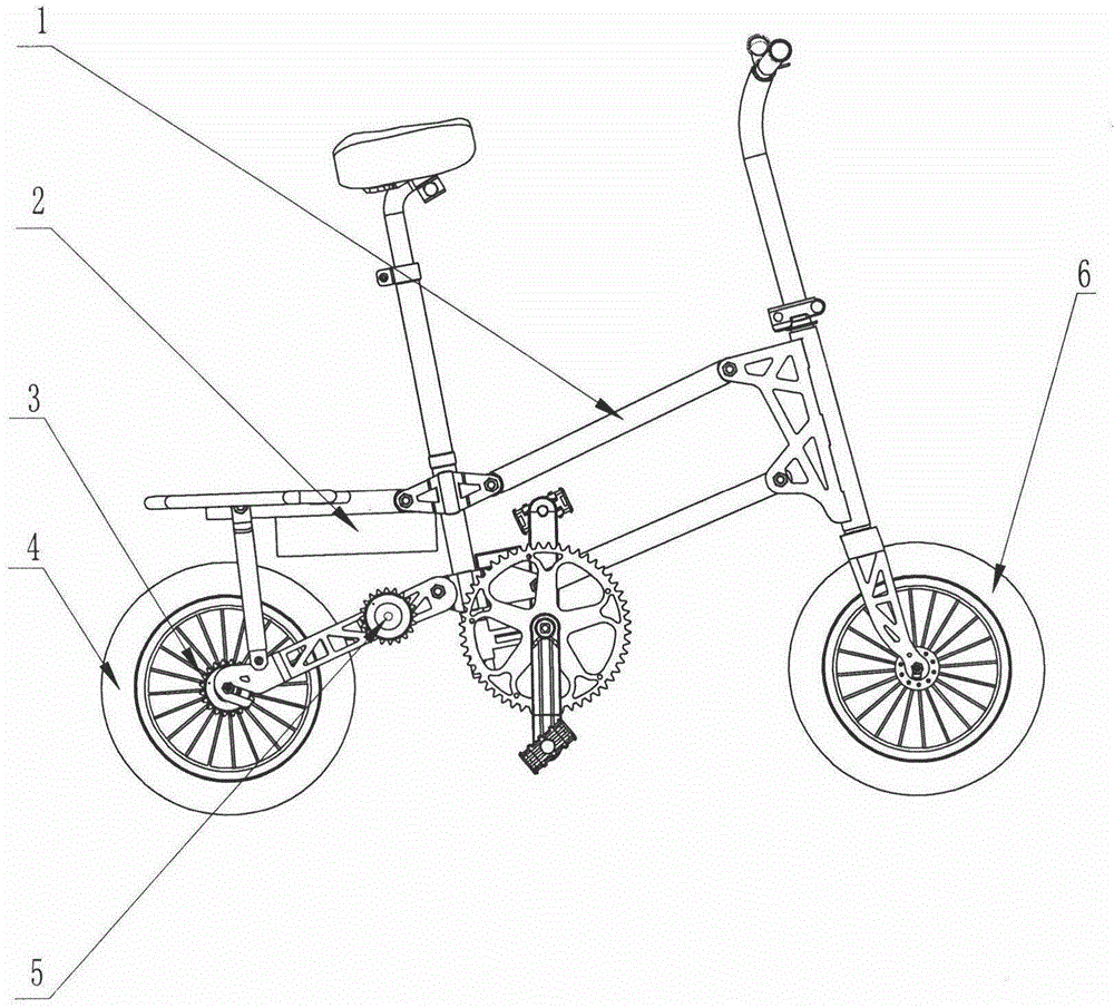
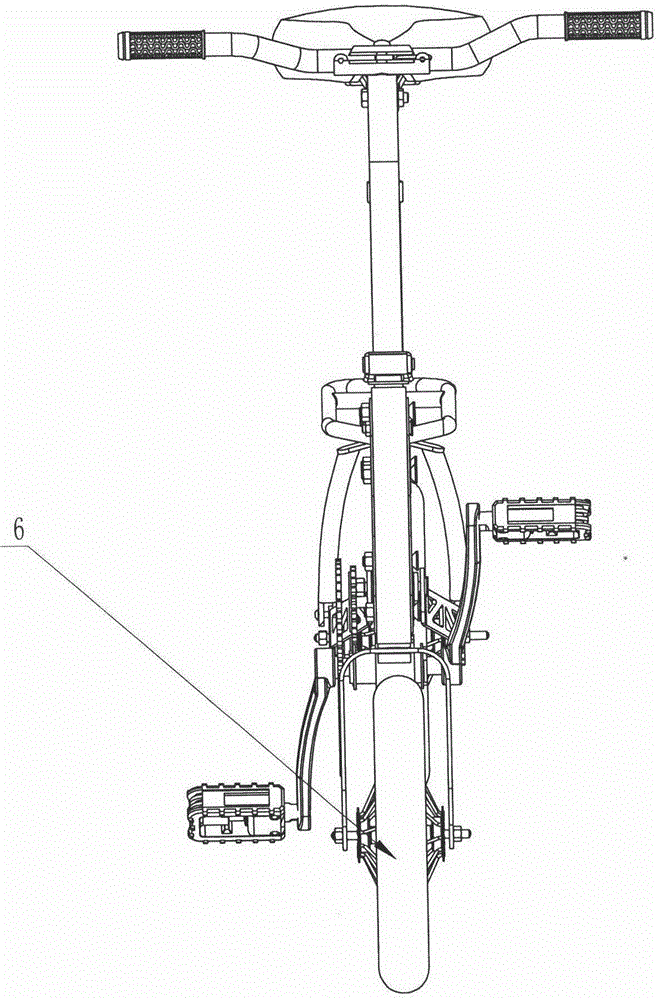
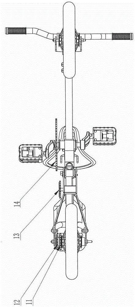
[0024] The present invention is an intelligent uniform force pedal bicycle, such as figure 1 , 2 , 3, 4, 5, 6, and 7, including: body system, electric drive system, flywheel chain drive system, control system, pedal dynamometer drive system, and brake system. It is characterized in that: the body system is that the front fork is installed on the front end of the vehicle frame 1 through the rotation of the headset, and the wheels 4 and 6 are installed on the vehicle frame 1 and the front fork through shafts and bearings; the electric drive system is The battery 2 is fixed on the frame 1, the positive and negative poles of the battery 2 are respectively connected to the controller 9 of the control system through wires, the motor 7 is fixed on the frame 1 through bolts, and the motor 7 is connected to the controller 9 of the control system through wire...


PUM


Abstract

Disclosed is an intelligent uniform-force pedal moped which comprises a body system, a motor drive system, a flywheel chain plate transmission system, a control system, a pedal force measurement driving system and a brake system. The intelligent uniform-force pedal moped is characterized in that according to the body system, a front fork is mounted at the front end of a frame, and wheels are mounted on the front and the front fork; according to the motor drive system, a battery is fixed on the frame, and a motor is fixed on the frame through bolts; according to the flywheel chain plate transmission system, a first flywheel and a second flywheel which are concentric with the rear wheel are fixedly connected to the rear wheel and on one side of the rear wheel, and a motor flywheel is fixed on a shaft of the motor; according to the pedal force measurement driving system, one ends of N force transducers are fixed on the frame while the other ends are fixedly connected with a middle axle fixing block, and a middle axle is rotationally mounted in a hole of the middle axle fixing block through a headset; according to the brake system, brake mechanisms are mounted on the front and rear wheels respectively.

Description

technical field [0001] The invention relates to an electric power-assisted vehicle, in particular to an intelligent uniform force pedal-assisted vehicle which has both the functions of an electric vehicle and a bicycle. Background technique [0002] At present, the power assist system of electric vehicles on the market is not a real power assist. When the pedal is stepped on, the motor will output a maximum force to the wheel. The magnitude of this force remains unchanged. To change the magnitude of this force, you need It is done through the accelerator; but when the battery is out of power, the boost will also disappear, but when you want to use the pedals to drive the wheels, the resistance at this time will be very large, which is very inconvenient to ride. Walking, the main source of this resistance is the magnetic resistance inside the drive motor on the driving wheel; in fact, when the wheels are driven by the accelerator, the resistance is greater when the wheels are...

Claims


Application Information

Patent Timeline
Patent Type & Authority Patents(China)
IPC IPC(8): B62M6/45B62M6/40
CPCB62M6/70B62K15/008
Inventor 王春阳
Owner HAIMEN THE YUECAI TEXTILE TECH CO LTD
Why Eureka
Try Eureka