
Heavy oil catalytic cracking method and heavy oil catalytic cracking equipment
A technology of catalytic cracking and heavy oil catalysis, which is applied in the direction of catalytic cracking, cracking, petroleum industry, etc., can solve the problems of increased coking rate, lower mixing temperature at the bottom, and increase of unvaporized oil, so as to reduce the coking rate and improve the Oil ratio, the effect of reducing unvaporized oil
- Summary
- Abstract
- Description
- Claims
- Application Information
AI Technical Summary
Problems solved by technology
Method used
Image

Examples
Embodiment Construction
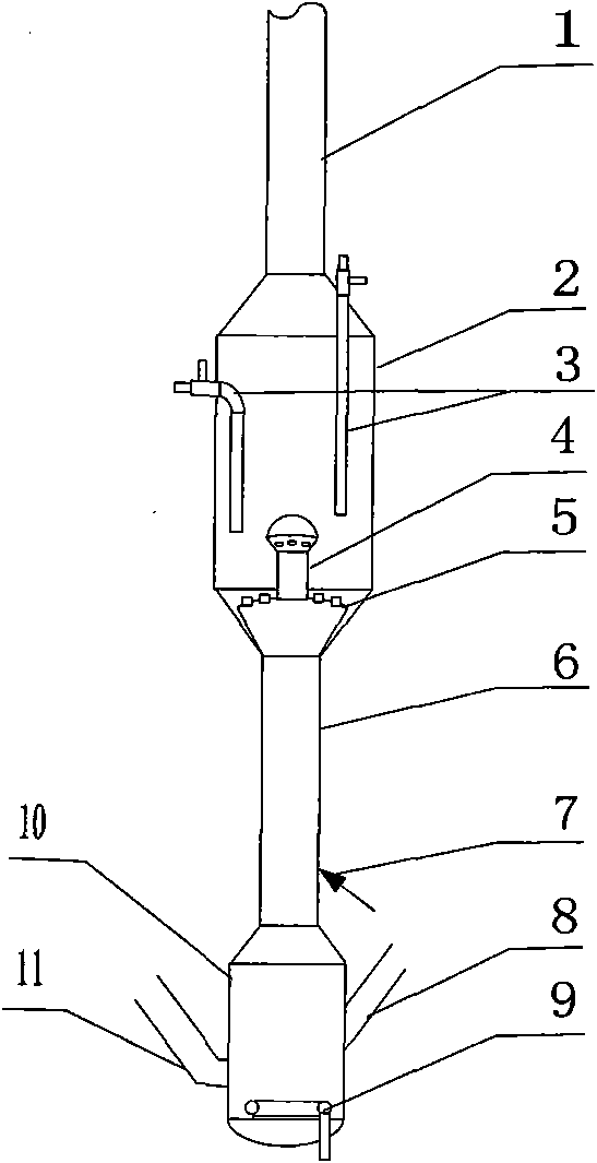
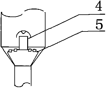
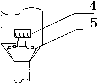
[0031] see Figure 1 ~ Figure 7 , The lower part of the pre-lifter 10 is provided with a fluidized medium loop tube 9, the lower side is connected with the catalyst feed pipe 8, and the upper end is connected with the cracking section 6. The upper end of the middle heat-taking section 2 is connected with the conveying pipe 1, and the lower end is connected with the cracking section 6. There are plate distributors 5 and mushroom distributors 4 (or umbrella hat distributor 4 or hat distributor 4 or column distributor 4 or tubular distributor 4), there is a feed nozzle 7 at the lower part of the cracking section 6. figure 1 , The middle heat-taking section 2 is provided with a heat-taking pipe 3 inside, and the lower part of the pre-lifter 10 is simultaneously connected with another catalyst feeding pipe 11; Image 6 , The middle heating section 2 is connected with the low-temperature regenerant delivery pipe 3, and the lower part of the pre-lifter 10 is simultaneously connected wi...
PUM
 Abstract
Description
Claims
Application Information