A self-excited soft start method for chain-type converter valve

A converter valve and soft start technology, applied in the direction of output power conversion devices, electrical components, etc., can solve the problems of weak grid system voltage distortion, adverse effects of operating equipment, large unlocking surge current, etc., to eliminate DC voltage inconsistency, The effect of eliminating overmodulation and ensuring safe operation

Active Publication Date: 2017-02-08
NR ELECTRIC CO LTD +1
View PDF6 Cites 0 Cited by
  • Summary
  • Abstract
  • Description
  • Claims
  • Application Information

AI Technical Summary

Problems solved by technology

The separately excited start-up is to charge the DC capacitors of the converter valve before grid connection through an additional auxiliary circuit, and realize the non-impact grid connection of the converter valve through the grid connection control algorithm, but its design is difficult and economical.
Self-excited start-up is to add a current-limiting reactor or resistor on the AC side of the converter valve to limit the charging surge current of the converter valve when it is connected to the grid, and unlock the normal operation after the DC voltage rises to the set threshold, but due to the primary circuit There are resistance voltage drop, diode voltage drop, etc., and the DC voltage is limited, which will lead to out-of-control behaviors such as over-modulation at the moment of unlocking, resulting in a large unlocking impulse current, resulting in voltage distortion of the weak grid system, and causing adverse effects on operating equipment

Method used


Image

  • A self-excited soft start method for chain-type converter valve
  • A self-excited soft start method for chain-type converter valve

Examples


Embodiment Construction

[0022] The technical solutions of the present invention will be described in detail below in conjunction with the accompanying drawings.

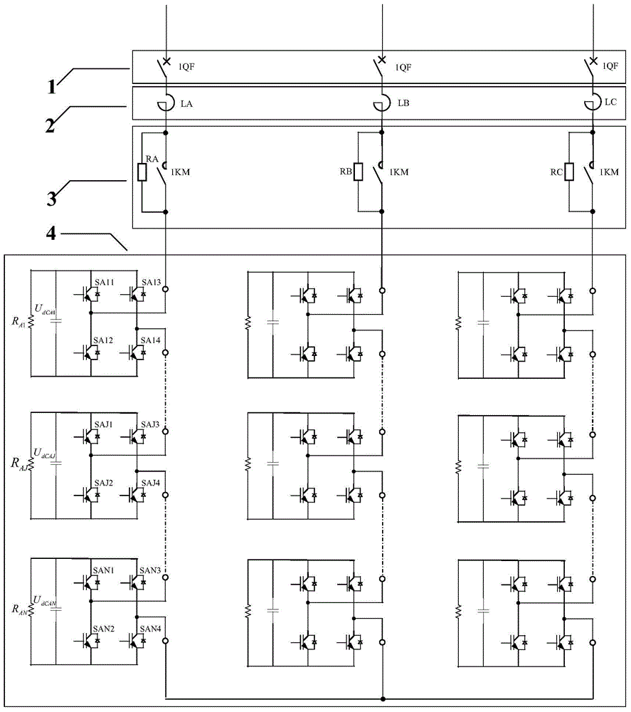
[0023] Such as figure 1 As shown, it is a self-excited soft start system of a chain converter valve based on the soft start method of the present invention, which is used to control the soft start of the chain converter valve 4. Taking phase A as an example, the chain The type converter valve is formed by cascading N power units, where N is a natural number; the soft start system includes a grid-connected circuit breaker 1, a reactor 2 and a starting circuit 3 connected in series, wherein the starting circuit 3 includes mutual A current-limiting resistor RA and a bypass switch 1KM are connected in parallel. The bypass switch can use a vacuum circuit breaker, a vacuum contactor or an isolation knife switch. The grid-connected circuit breaker 1 is used as the DC capacitor of each power unit in the chain-type converter valve. Charging does no...


PUM


Abstract

The invention discloses a self-excitation soft start method for a chain-type converter valve. The soft start system comprises a grid-connected circuit breaker, an electric reactor and a starting circuit which correspond to each phase and are connected in series with one another. The soft start method comprises the following steps: controlling to close the grid-connected circuit breaker, so that direct current capacitors of power units of the chain-type converter valve are charged for the first time by a power grid by virtue of a current-limiting resistor; controlling to switch on a by-pass switch, bypassing the current-limiting resistor, selecting at least one power unit from various power units of the converter valve, and bypassing the selected power units, so that the non-bypassed direct current capacitors of power units are charged by the power grid; unlocking the chain-type converter valve, and allowing the chain-type converter valve to enter a direct current voltage closed loop to control the operation; and judging that the direct current voltage of each power unit is stabilized at a value needed by normal operation, and transferring into a closed loop of a control target to control the operation. According to the method, the direct current voltage of each unit can be effectively improved before the converter valve is started, the start impact current of the converter valve is effectively reduced, the direct current voltage balancing control of the converter valve is promoted, and the safety operation of a power device is guaranteed.

Description

technical field [0001] The invention belongs to the field of electrical automation equipment, and in particular relates to a self-excited soft start method for a chain-type converter valve. Background technique [0002] High-power power electronic conversion technology is more and more widely used in power systems. Limited by the technical level of power electronic power devices, high-power power electronic equipment directly connected to medium and high voltage power grids mostly use power devices in direct series connection or specific structural valves. The topology of unit cascading and the chain topology of valve unit cascading reduce the requirements for the consistency of power device parameters and reduce the difficulty of designing the secondary control loop. It is a circuit structure that is easier to engineer, and its representative is a single-phase full bridge A static var generator composed of cascaded units, and a modular multilevel flexible DC converter valve...

Claims


Application Information

Patent Timeline
Patent Type & Authority Patents(China)
IPC IPC(8): H02M1/36
CPCH02M1/36
Inventor 盛晓东谢晔源吴小丹王翀吴扣林魏星方太勋刘为群汪涛
Owner NR ELECTRIC CO LTD
Why Eureka
Try Eureka