In-situ combustion layered ignition method

A technology for burning oil layers and oil layers, which is used in earth-moving drilling, fluid production, wellbore/well components, etc. The effect of ignition efficiency, reduction of high temperature time, and improvement of ignition effect

Active Publication Date: 2015-03-25
PETROCHINA CO LTD
View PDF7 Cites 10 Cited by
  • Summary
  • Abstract
  • Description
  • Claims
  • Application Information

AI Technical Summary

Problems solved by technology

However, these two ignition methods have the following problems: the success rate of ignition is not high
Because the remaining oil saturation near the wellbore is low and the water content is high, at the initial stage of ignition, the water evaporates and takes away a large part of the heat, and the temperature of the oil layer reaching the ignition point is 360°C to 420°C. Therefore, long-term low-temperature oxidation is required to achieve this Due to the long time of low-temperature oxidation (the heat generated by low-temperature oxidation < the heat absorbed by the formation + the heat taken away by the air), some oil wells failed to reach the ignition point temperature of the oil layer. If the oil layer after the fire is re-ignited, the difficulty will be Greatly increased, and if the two layers are not lit at the same time, the follow-up operation will be more difficult

Method used


Image

  • In-situ combustion layered ignition method
  • In-situ combustion layered ignition method
  • In-situ combustion layered ignition method

Examples


Embodiment Construction

[0018] The following will clearly and completely describe the technical solutions in the embodiments of the present invention with reference to the accompanying drawings in the embodiments of the present invention. Obviously, the described embodiments are only some, not all, embodiments of the present invention. Based on the embodiments of the present invention, all other embodiments obtained by persons of ordinary skill in the art without creative efforts fall within the protection scope of the present invention.

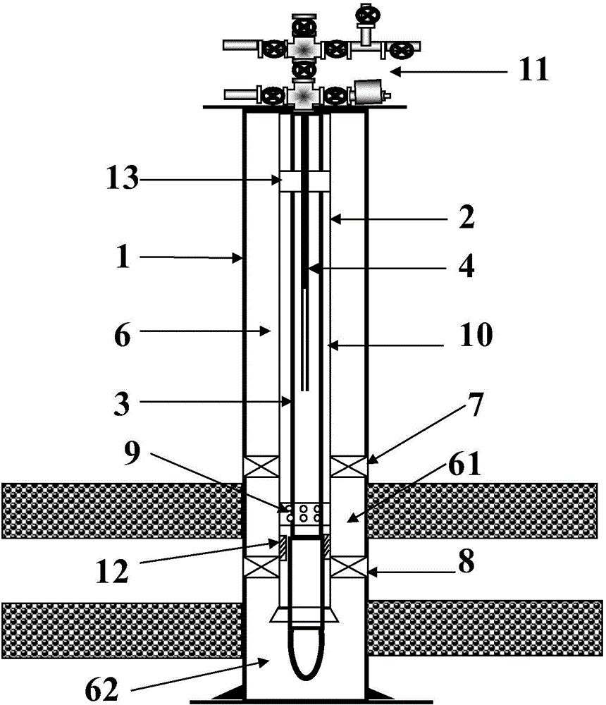
[0019] An embodiment of the present invention provides a method for stratified ignition of a combustion oil layer. The present invention will be described in detail below in conjunction with the accompanying drawings.

[0020] The embodiment of the present invention provides a method for stratified ignition of incineration oil layer. In practical application, the method for stratified ignition of incineration oil layer can be specifically applied to figure 1 , F...


PUM


Abstract

The invention provides an in-situ combustion layered ignition method. The method includes the steps that a casing pipe is landed into an oil well and extends to the well bottom; a thermal insulation pipe is landed into the casing pipe and a first annular space is formed between the thermal insulation pipe and the casing pipe; the first annular space is sealed through a first packer and a second packer, so that an upper-layer gas injection space and a lower-layer gas injection space are formed; an upper-layer gas distribution device located in the upper-layer gas injection space is arranged on the thermal insulation pipe; a Pupin oil pipe is landed into the thermal insulation pipe, a second annular space is formed between the Pupin oil pipe and the thermal insulation pipe, and an enhanced heat transfer device is arranged in the second annular space; an electric ignition device is landed in an inner cavity of the Pupin oil pipe; air is injected in the inner cavity and the second annular space and nitrogen is injected into the first annular space; the electric ignition device is started; heated gas in the thermal insulation pipe is injected into the upper-layer gas injection space through the upper-layer gas distribution device and an upper oil layer is heated and ignited; heated gas in the Pupin oil pipe is injected into the lower-layer gas injection space through the tail end of the Pupin oil pipe and a lower oil layer is heated and ignited.

Description

technical field [0001] The present invention relates to a combustion oil layer ignition technology, in particular to a layered ignition method for combustion oil layers. Background technique [0002] At present, the ignition techniques commonly used in heavy oil reservoirs mainly include steam injection spontaneous ignition, steam injection + chemical agent combustion-assisted ignition, and mobile electric ignition. However, some blocks in the fire-burning oil layer are multi-layer fires, and layered ignition and gas injection are required. Due to the limited space of the pipe string for layered injection, it is impossible to implement layered ignition with a mobile electric igniter. Therefore, the layered ignition on site The main methods are steam injection spontaneous ignition and steam injection + chemical agent combustion-assisted ignition. However, these two ignition methods have the following problems: the success rate of ignition is not high. Because the remaining ...

Claims


Application Information

Patent Timeline
Patent Type & Authority Applications(China)
IPC IPC(8): E21B43/243
CPCE21B43/243
Inventor 于晓聪阚长宾杨宝春龙华郝瑞辉刘锦马薇赵树杰汪小平杨显志孙鹿恒陈东明黄小雷刘江玲闫绪鹏吕政关泽寰
Owner PETROCHINA CO LTD
Why Eureka
Try Eureka