Chassis bracket device for cabinet

A technology of bracket device and chassis, applied in the direction of support structure installation, etc., can solve the problems of poor boosting ability and unrestricted boosting force, and achieve the effect of solving the poor boosting ability

Active Publication Date: 2015-04-08
CHINA AVIATION OPTICAL-ELECTRICAL TECH CO LTD
View PDF7 Cites 3 Cited by
  • Summary
  • Abstract
  • Description
  • Claims
  • Application Information

AI Technical Summary

Problems solved by technology

[0005] The purpose of the present invention is to provide a chassis bracket device for cabinets, so as to solve the problems that the existing chassis bracket devices used for electrical cabinets have poor boosting ability and can not limit the force of boosting

Method used


Image

  • Chassis bracket device for cabinet
  • Chassis bracket device for cabinet
  • Chassis bracket device for cabinet

Examples


Embodiment Construction

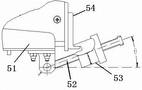
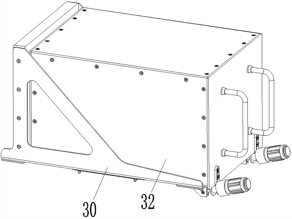
[0026] An embodiment of a chassis bracket device for a cabinet, such as Figure 2-12 As shown, the chassis bracket device includes a bracket 30 and a locking device.

[0027] The structure of the bracket is the prior art, and will not be described in detail here, and the locking device is assembled on the front part of the bracket.

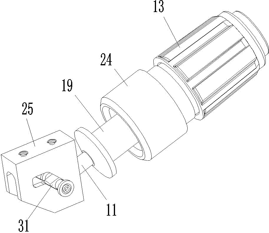
[0028] The locking device includes a locking rod 11, a screw sleeve 12, a screw cap 13, a transmission steel ball 14, a transmission plate 15, a pressure plate 16, a force limiting spring 17, a spring support sleeve 18, an output sleeve 19, a transmission seat 20, a ball 21, Push spring 22, transmission sleeve 23, lock cap 24 and lock seat 25.

[0029] The front end of the locking rod 11 is provided with a hinge hole and a threaded section is provided between the two ends.

[0030] The position between the two ends of the screw sleeve 12 is provided with an internal thread segment, which corresponds to the thread segment on the lock bar 11, and ...


PUM


Abstract

The invention relates to the field of a modularized electric cabinet and especially relates to a chassis bracket device for a cabinet. The chassis bracket device for the cabinet comprises a bracket and a locker assembled on a front part of the bracket, wherein the locker comprises a lock rod and a lock cap; a locking opening is formed in the front end of the lock cap; a thread sleeve is threaded on the lock rod; a force-limiting spring, a pressing slice, a driving slice, a rotary cap and an output sleeve are also arranged on the thread sleeve; a stopping wall is arranged between the two ends of the rotary cap; a mounting hole is formed in the stopping wall; a driving steel ball is arranged in the mounting hole; the pressing slice and the driving slice are respectively arranged on the two sides of the stopping wall; the driving slice and the thread sleeve are in rotation-stopping fit with each other; a ball slot corresponding to the steel ball is formed in the driving slice; the force-limiting spring is jacked between one side of the pressing slice away from the steel ball and the thread sleeve; a locking hook pushing pressing structure which is matched with a locking hook on the corresponding chassis and is used for pushing the chassis is arranged on the output sleeve; a transmitting structure which is used for driving the output sleeve to move forward is arranged on the thread sleeve. The chassis bracket device is used for solving the problem of poor boosting capacity and incapacity of limiting force through boosting of the present chassis bracket device for the cabinet.

Description

technical field [0001] The invention relates to the field of modular electrical cabinets, in particular to a cabinet bracket device for the cabinet. Background technique [0002] With the development of modularization and miniaturization of various electronic equipment, electronic equipment cabinets have been widely used in electronic equipment cabinets (electrical cabinets). In the specific use process, in order to realize the overall loading and unloading and replacement, the cabinet is equipped with a chassis bracket device in layers. The electrical connector provided in the cabinet cooperates with the electrical connector on the chassis bracket provided in the cabinet to realize the introduction of the electronic equipment chassis. This structure requires that the electronic equipment chassis must have a reliable fixing mechanism when it is assembled on the cabinet. Therefore, the chassis The bracket devices all include a bracket and a locking device assembled on the br...

Claims


Application Information

Patent Timeline
Patent Type & Authority Applications(China)
IPC IPC(8): H05K7/14
Inventor 周卫可吕云朋陈建超杨成博
Owner CHINA AVIATION OPTICAL-ELECTRICAL TECH CO LTD
Why Eureka
Try Eureka