This helps you quickly interpret patents by identifying the three key elements:
Problems solved by technology
Method used
Benefits of technology
Problems solved by technology
[0010] Therefore, it should be appreciated that existing lighting control systems lack the precision to allow the driver to easily turn on the appropriate exterior running lights
Method used
Image
Click on the blue label to locate the original text in one second.
Reading with bidirectional positioning of images and text.
Examples
example 1
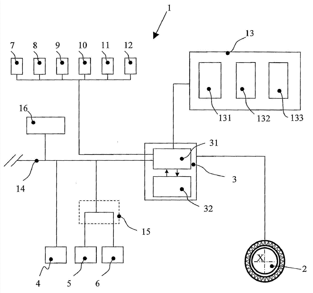
[0250] according to figure 1 &2, Table 1 and according to Figure 5 The method described in Example 1 below describes.
[0251] Due to the environmental parameter data received by the controller 3 from the sensors 4, 5, 6, the controller 3 can determine that it is raining (second column in Table 1, step 201), and from several available lighting configurations (the first list ) to select a suitable lighting configuration (the third column in Table 1, step 202):
[0252] ·DRL ON
[0253] ·Position light ON
[0254] · Low beam ON
[0255] The name of this choice is identified as rainy day choice (second column in Table 1). By performing this selection, the controller 3 avoids selecting some lighting configurations that are useless or unsafe when it is raining, or that might confuse a driver who needs to select a new lighting configuration.
[0256] Control 3 then assigns to each selected lighting configuration a lighting configuration level (fourth column in Table 1, step 2...
PUM
Abstract
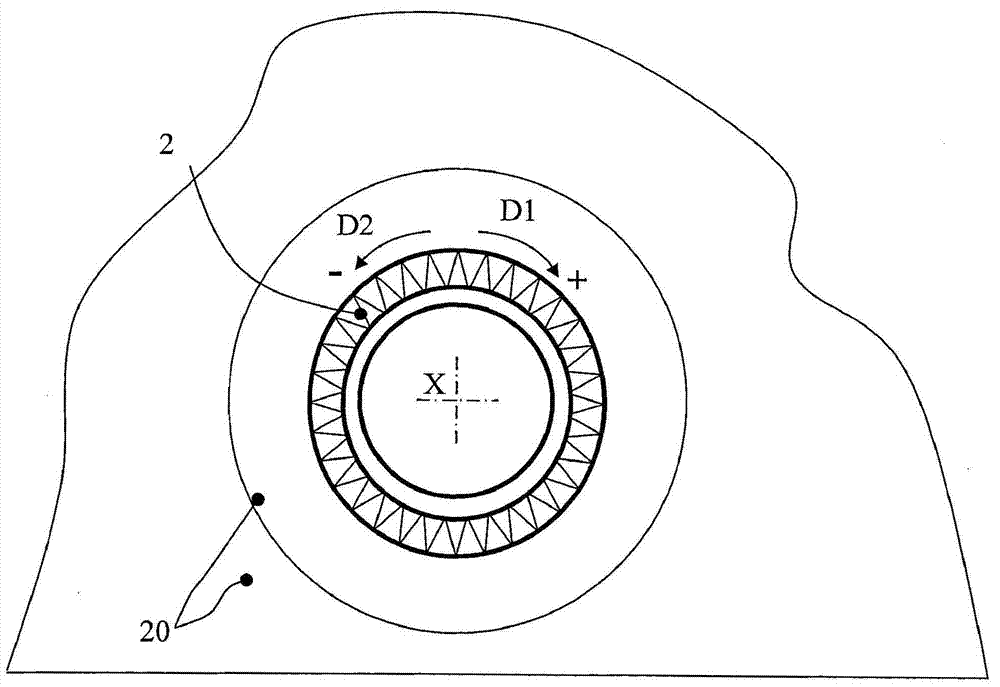
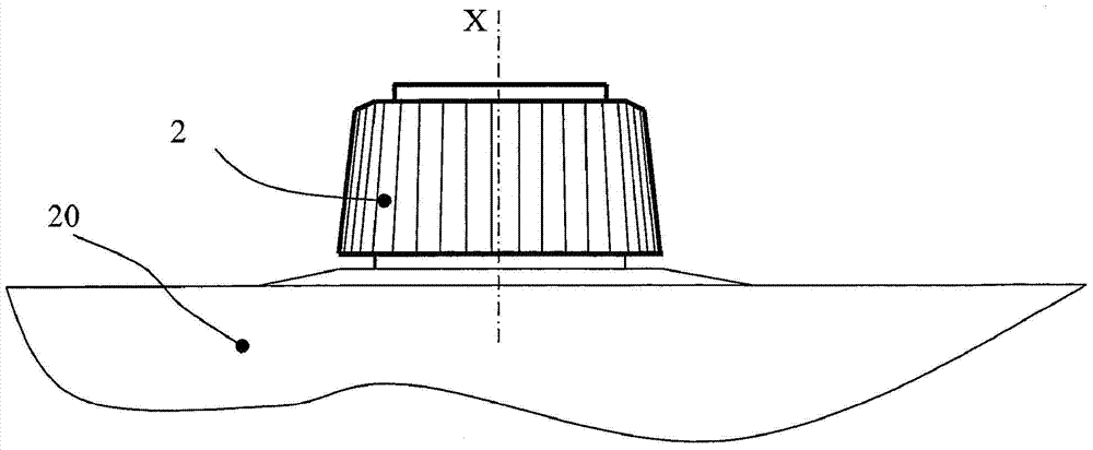
The invention relates to a lighting control system and a lighting control method for implementing exterior running lights (7‑12) in different available lighting configurations in a motor vehicle. The lighting control method comprises the steps of: a) detecting at least one environmental parameter (101, 201, 301); b) selecting from among different available lighting configurations and depending on said parameter which lighting configuration can be implemented (102, 202, 302); c) upon manual actuation of the input means (2, 21, 22, 23, 24, 25), depending on said parameter defines in which order the selected lighting configurations (103, 203, 303) are implemented; d) detect (104, 204, 309) manual actuation on input means (2, 21, 22, 23, 24, 25); e) depend on input means (2, 21, 22, 23, 24, 25) The movement of the input device or the movement on the input device implements at least one lighting configuration (105, 206, 310) selected among the selected lighting configurations according to the implementation sequence.
Description
technical field [0001] The invention relates to a lighting control system and a lighting control method for implementing and controlling exterior running lights of a motor vehicle. Background technique [0002] Traditionally, exterior running lights are controlled by rotary switches or stalk switches. These switches are mechanical systems that can have multiple physical positions, each of which corresponds to the illumination state of the exterior running lights. [0003] Typically, in the case of a rotary switch or a stalk switch, the first switch position indicates the OFF position of the lamp; the second switch position indicates the position lamp ON, and the third position indicates the low beam / high beam ON. [0004] Modern vehicles can further be equipped with light sensors capable of detecting the intensity of daylight. Based on the information detected by the sensors, the vehicle controller can turn on the lights as position lights or dipped beam without any input ...
Claims
Application Information
Patent Timeline
Application Date:The date an application was filed.
Publication Date:The date a patent or application was officially published.
First Publication Date:The earliest publication date of a patent with the same application number.
Issue Date:Publication date of the patent grant document.
PCT Entry Date:The Entry date of PCT National Phase.
Estimated Expiry Date:The statutory expiry date of a patent right according to the Patent Law, and it is the longest term of protection that the patent right can achieve without the termination of the patent right due to other reasons(Term extension factor has been taken into account ).
Invalid Date:Actual expiry date is based on effective date or publication date of legal transaction data of invalid patent.

