Automatic feeding device for brake wheels of clutches of washing machines

A technology of automatic feeding and braking wheels, which is applied to washing devices, other washing machines, loading/unloading, etc., can solve the problems of high labor intensity and heavy labor load of loading workers, and achieve the effect of high reliability

Inactive Publication Date: 2015-05-13
ZHEJIANG UNIV
View PDF8 Cites 2 Cited by
  • Summary
  • Abstract
  • Description
  • Claims
  • Application Information

AI Technical Summary

Problems solved by technology

[0003] At present, the brake wheel is manually placed on the conveyor belt equipped with fixed fixtures in the industrial site of foreign advanced washing machine enterprises. Due to the fast pace of the clutch assembly line, the labor load of the loading workers is large, and no delay is allowed. In domestic washing machine companies, most of the parts are picked and placed manually, which is more labor-intensive

Method used


Image

  • Automatic feeding device for brake wheels of clutches of washing machines
  • Automatic feeding device for brake wheels of clutches of washing machines
  • Automatic feeding device for brake wheels of clutches of washing machines

Examples


Embodiment Construction

[0035] Below in conjunction with accompanying drawing and embodiment the present invention is described in further detail:

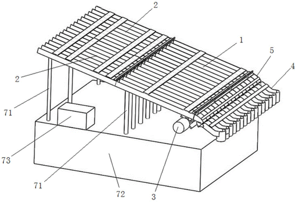
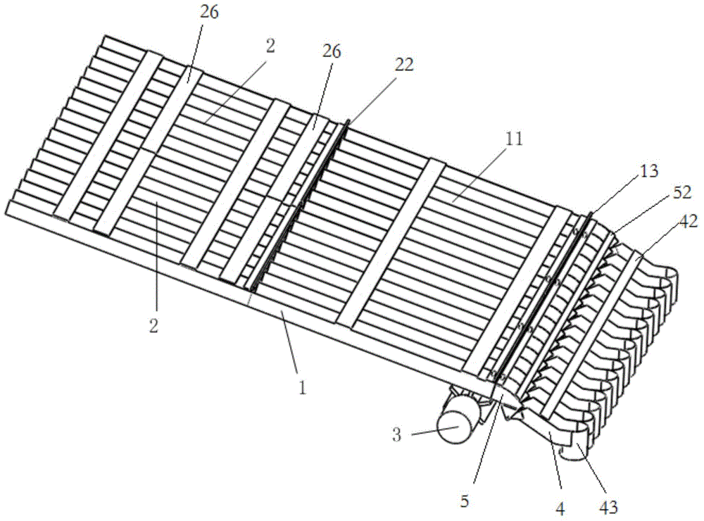
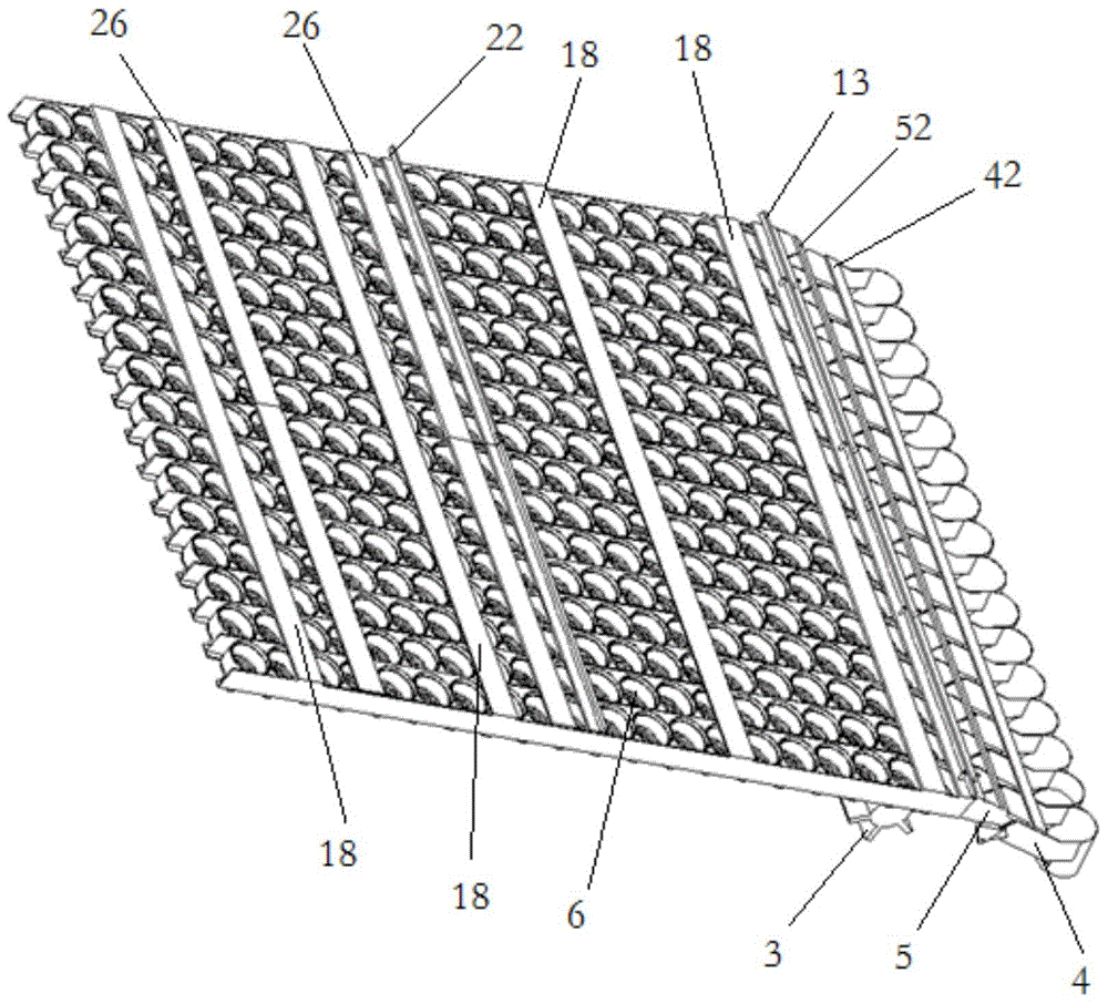
[0036] refer to Figure 1-10 : The automatic feeding device for the clutch brake wheel of the washing machine, including an inclined silo 1, the front of the inclined silo 1 is inclined downward, and the front part of the inclined silo 1 is arranged side by side with a plurality of first slides for the single row of brake wheels to slide. Rail 11, the first slide rail 11 is horizontally arranged, and the rear portion of inclined feed bin 1 is provided with support rail 12, and support rail 12 is inserted in the rear portion of inclined feed bin 1 side by side for a plurality of movable feed bins 2, and movable feed bin 2 It can be extracted and set on the support rail 12, and each movable bin 2 has a plurality of second slide rails 21 for single-row brake wheels to slide, and the exit of the second slide rail 21 corresponds to the entrance of the first s...


PUM


Abstract

An automatic feeding device for brake wheels of clutches of washing machines comprises an oblique bin, wherein multiple first sliding rails allowing the brake wheels to slide thereon are arranged in front of the oblique bin in parallel, a supporting rail allowing multiple movable bins to be inserted therein is arranged behind the oblique bin, each movable bin is provided with multiple second sliding rails, and an outlet of each second sliding ail corresponds to an inlet of the corresponding first sliding rail; a vane wheel used for shifting the brake wheels on the longitudinal row is arranged at the bottom end of the oblique bin, an outlet of the oblique bin is connected with a discharging mechanism which is provided with third sliding rails corresponding to the first sliding rails, a cylindrical discharge outlet is formed in the tail end of each third sliding rail, and the brake wheels slide along the third sliding rails and fall down through the cylindrical discharge outlets; sliding ports matched with the small ends of the brake wheels are formed in the bottom ends of the first sliding rails, the bottom ends of the second sliding rails and the bottom ends of the third sliding rails, and the width of each first sliding rail, the width of each second sliding rail and the width of each third sliding rail are matched with the large end of each brake wheel. The device has the advantage that automatic feeding of brake wheels of clutches of washing machines can be achieved and is used in cooperation with a clutch assembly line.

Description

technical field [0001] The invention relates to an automatic feeding device for a clutch brake wheel of a washing machine. Background technique [0002] As a necessary household appliance in modern life, the washing machine has a huge output, and the brake wheel is a key component of the clutch of the washing machine, and its feeding process has become a bottleneck restricting the automation of the clutch assembly line. The brake wheel of the washing machine clutch is composed of two cylinders with different diameters, which are in an inverted convex shape. The upper cylinder constitutes the large end of the brake wheel, and the lower cylinder constitutes the small end of the brake wheel. Due to the irregular shape of the part, At present, there is no automatic feeding device that can completely liberate the loading workers. [0003] At present, the brake wheel is manually placed on the conveyor belt equipped with fixed fixtures in the industrial site of foreign advanced wa...

Claims


Application Information

Patent Timeline
Patent Type & Authority Applications(China)
IPC IPC(8): B65G65/32B65G65/40B65G47/24D06F37/30
CPCB65G47/1407
Inventor 靳兴来朱世强裴祥金丁灿
Owner ZHEJIANG UNIV
Why Eureka
Try Eureka