
Die

A mold and template technology, applied in the field of tooling, can solve problems such as disadvantages and reduce mold costs, and achieve the effect of reducing the size of the template and saving the structure of the fixing seat

Active Publication Date: 2015-05-27
GREE ELECTRIC APPLIANCES INC
View PDF6 Cites 0 Cited by
  • Summary
  • Abstract
  • Description
  • Claims
  • Application Information

AI Technical Summary

Problems solved by technology

[0003] Disadvantages of the prior art: In the process of design and manufacture, it is necessary to consider the strength of the fixing seat and the template to ensure the smooth movement of the slider drive mechanism
However, in the prior art, since it is necessary to provide fixing seat grooves and screw holes on the formwork, the formwork is often one level larger than the actual need, which is not conducive to reducing the cost of the mold.

Method used

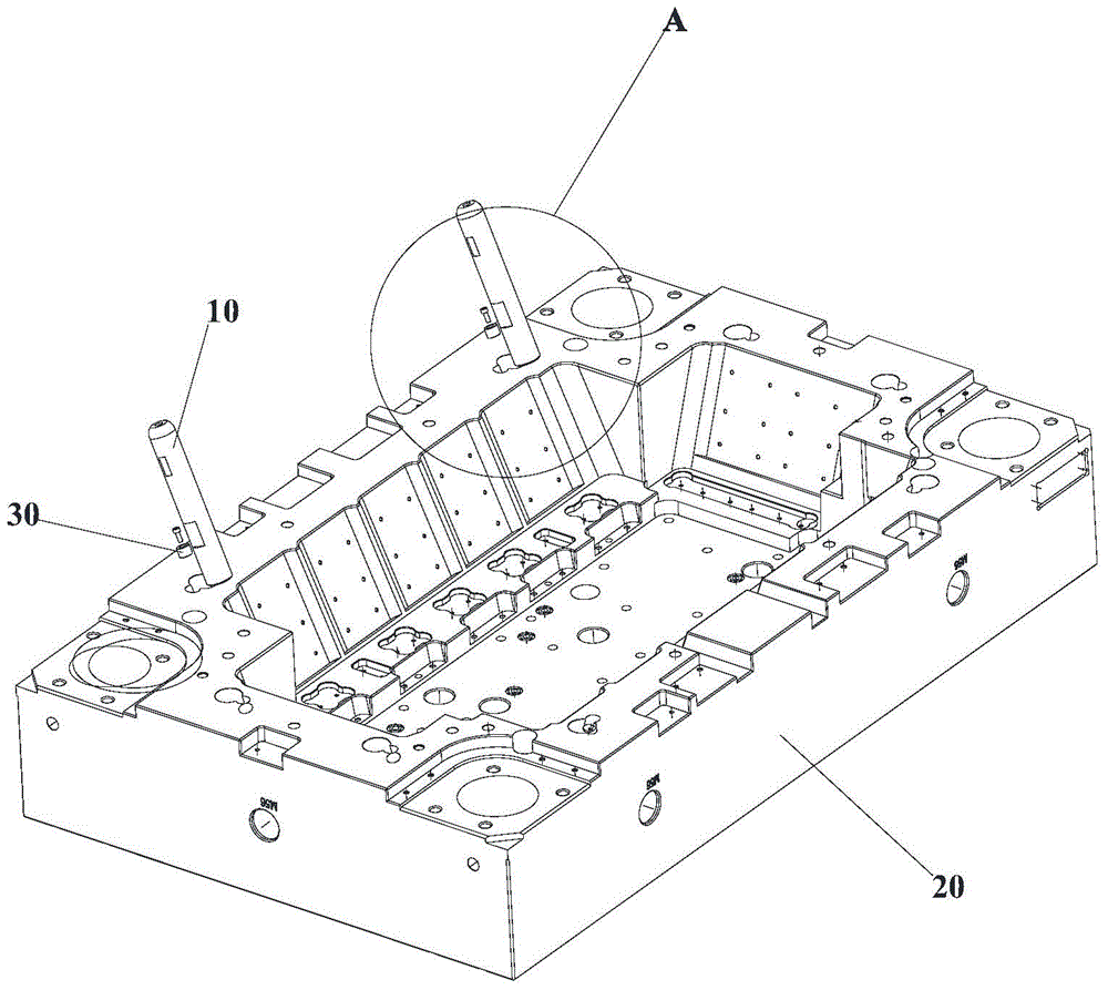
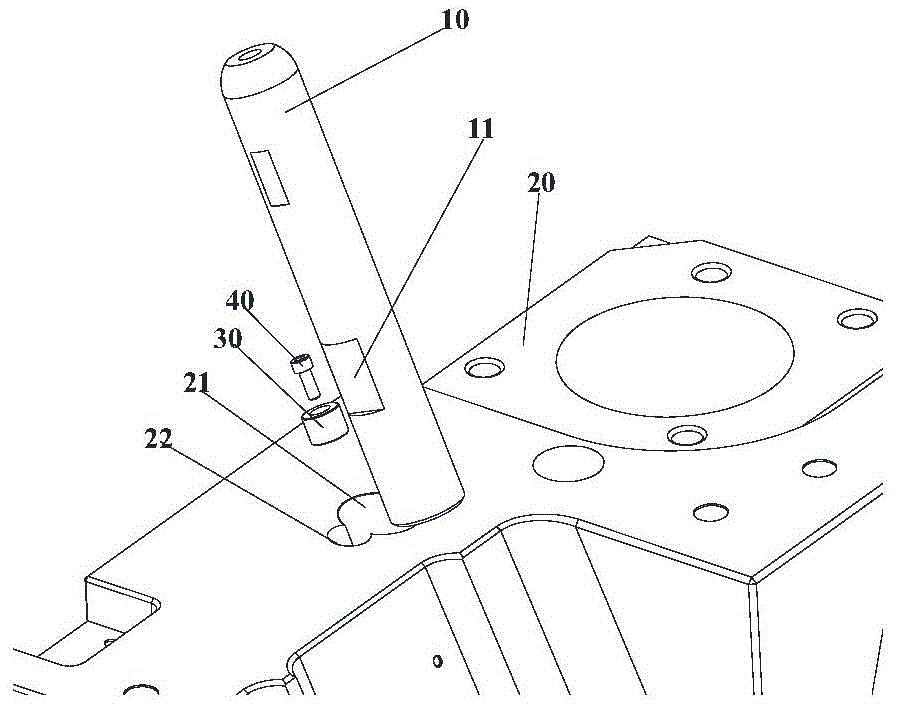
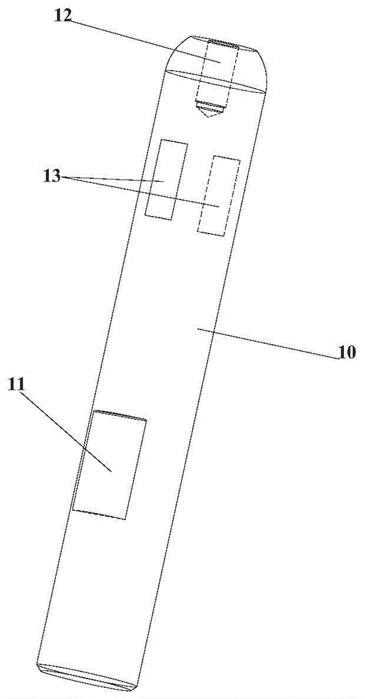

Image

  • Die
  • Die
  • Die

Examples


Embodiment Construction

[0022] It should be noted that, in the case of no conflict, the embodiments in the present application and the features in the embodiments can be combined with each other. The present invention will be described in detail below with reference to the accompanying drawings and examples.

[0023] Such as Figure 1 to Figure 4 As shown, the present invention provides a mold, including a guide column 10 , a template 20 and a fixing part 30 . The template 20 is provided with a guide post hole 21 , and the guide post 10 has a mounting section placed in the guide post hole 21 and a guide section located outside the guide post hole 21 . The fixing part 30 is detachably installed in the guide column hole 21 on the template 20 to limit the axial movement of the guide column 10 .

[0024] By setting the guide post hole 21 for accommodating the guide post 10 and the fixing part 30 for restricting the axial movement of the guide post 10, the guide post 10 can be directly matched with the ...


PUM


Abstract

The invention provides a die. The die comprises a die plate equipped with a guide column hole, a guide column which is equipped with a mounting section in the guide column hole and a guide section at the outside of the guide column hole, and a fixing part which is detachably mounted into the guide column hole in the die plate to limit the axial moving of the guide column. According to the die, the guide column hole for storing the guide column is formed, the fixing part for limiting the axial moving of the guide column is arranged, and therefore, the guide column can be directly matched with the guide column hole, and as a result, the fixing seat structure in the prior art can be saved; the die plate can be small in size, so that the purpose of reducing the size of the die plate on the premise that the die strength is met is reached.

Description

technical field [0001] The invention relates to the field of tooling, in particular to a mold. Background technique [0002] The guide column of the slider drive mechanism is fixed by using a fixed seat to cover the outer peripheral surface of the guide column, and then use four screws to fix the fixed seat on the template to play the role of fixing the guide column. In this way, to fix a guide column, a fixing seat needs to be processed, and corresponding fixing seat grooves and screw holes need to be processed on the template to accommodate the above-mentioned structure. [0003] Disadvantages of the prior art: In the process of design and manufacture, it is necessary to consider the strength of the fixing seat and the formwork to ensure the smooth movement of the slider driving mechanism. However, in the prior art, since it is necessary to provide fixing seat grooves and screw holes on the formwork, the formwork is often one grade larger than the actual need, which is no...

Claims


Application Information

Patent Timeline
IPC IPC(8): B21D37/12
CPCB21D37/12
Inventor 王巧华柯晓义王双华郑迪文
Owner GREE ELECTRIC APPLIANCES INC
Learn More