
Accuracy calibration device and accuracy calibration method of fixture for box-type parts
A technology of calibration device and parts clip, which is applied to feeding devices, automatic control devices, metal processing machinery parts, etc., can solve the problems of unstable welding quality, low adjustment efficiency, difficulty in positioning and adjustment of threshold assemblies, etc., and achieve accurate calibration. High efficiency, good safety, and the effect of not easy chip contamination
- Summary
- Abstract
- Description
- Claims
- Application Information
AI Technical Summary
Problems solved by technology
Method used
Image

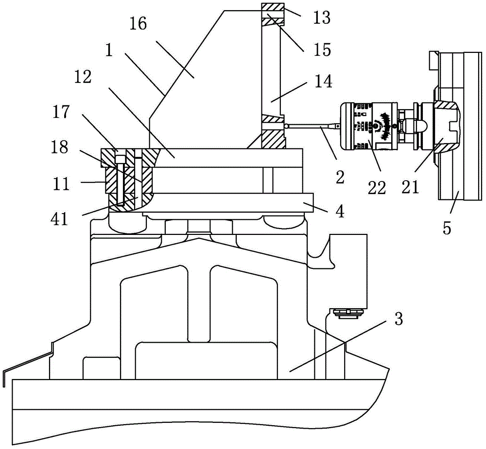
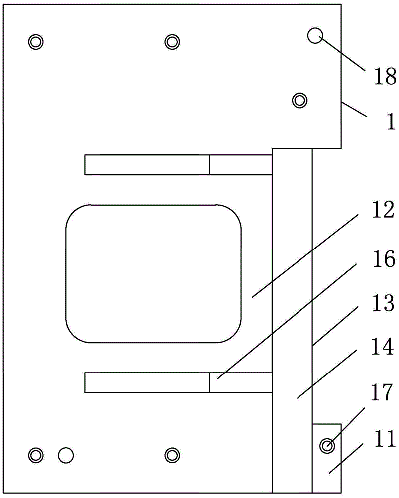
Examples
Embodiment Construction
[0014] The present invention will be further described below in conjunction with the accompanying drawings.
[0015] as attached figure 1 , attached figure 2 Shown: a precision calibration device for fixtures of box-type parts, including a precision calibration seat 1, an infrared probe system; the precision calibration seat 1 includes a bottom plate 12 with four connecting blocks 11 on the lower end surface, and a bottom plate 12 on one end surface. Vertical calibration surface 13 and the calibration vertical plate 14 that the lower end is welded with the base plate 12; The reinforcing plate 16 welded with the upper end surface of the bottom plate 12. In this embodiment, there are two calibration surfaces 13 arranged side by side; two calibration holes 15 are located on one calibration surface 13 . The lower end surface of each connection block 11 is provided with the connection through hole 17 that runs through the upper end surface of the base plate 12; the lower end su...
PUM
 Abstract
Description
Claims
Application Information