Antenna system for radio microphones

An antenna system, microphone technology, applied in transmission systems, electrical components, network improvements to reduce the impact of temperature changes, etc., capable of solving problems such as noise factor and/or interception of adverse effects

Active Publication Date: 2019-02-22
AKG ACOUSTICS
View PDF5 Cites 0 Cited by
  • Summary
  • Abstract
  • Description
  • Claims
  • Application Information

AI Technical Summary

Problems solved by technology

Also, these controllable attenuators generally have an adverse effect on noise figure and / or intercept

Method used


Image

  • Antenna system for radio microphones
  • Antenna system for radio microphones
  • Antenna system for radio microphones

Examples


Embodiment

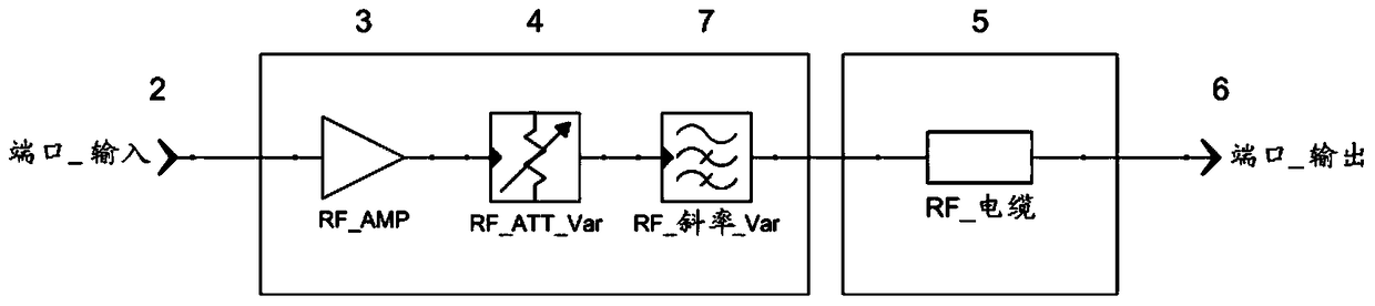
[0050] If you have an amplifier with a gain of 17dB, a series circuit of amplifier, properly chosen slope attenuator and RF cable (length in 1dB steps) will always give a constant frequency response around 0dB.

[0051] However, since initially it is not known which adjustment should be chosen for the slope attenuator (cable length is unknown), it is necessary to simply compare the values ​​of the two RF level meters to each other and the slope attenuator to vary until the two measured values ​​are the same or until the difference is minimized.

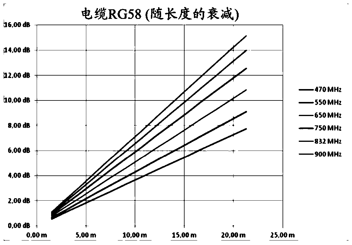
[0052] By limiting the above-mentioned cable types to specified qualities, it is thus possible to use measurements at any frequency point to optimally tune systems with unknown cable lengths.

[0053] If this limitation does not apply to certain RF cables, the base attenuation and slope must be measured at at least two frequency points and adjusted separately from each other.

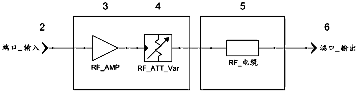
[0054] The antenna system may eg consist of a booster (=...


PUM


Abstract

The invention relates to an antenna system for a radio microphone comprising an antenna path starting at an input port (2) and ending at an output port (6), the antenna path having an amplifier (3) and an RF cable (5). To compensate for various cable attenuations, an attenuator (4) is provided between the amplifier (3) and the RF cable (5) in series with a variable slope compensator (7). In order to avoid the negative impact on large signal behavior of variable slope compensators according to the prior art, FETs or pin diodes or similar "microswitches" are used to switch resistors, but only as pure switches with no effect on the signal, to Achieve excellent large-signal behavior.

Description

technical field [0001] The invention relates to a radio microphone, in particular its antenna system according to the preamble of claim 1 and US Pat. No. 5,144,267. Background technique [0002] Different cable attenuations occur in antenna systems of radio microphones. This has to be taken into account, in which case amplification control is required in the antenna to compensate for cable attenuation by means of active components in order to maintain the best possible combination of interception and noise figure. Due to the frequency-dependent attenuation of the cables in the antenna system, an optimal combination of interception and noise figure is only possible at one frequency point in a broadband amplifier, regardless of whether it is controllable or constant amplification. To this, it must be added that the slope of the frequency-dependent attenuation varies with the cable length, so that an additional parameter has to be considered. [0003] This so-called slope com...

Claims


Application Information

Patent Timeline
Patent Type & Authority Patents(China)
IPC IPC(8): H03H11/02H03H11/54
CPCH04B1/18H04R2420/07H04R1/08H04R2499/11
Inventor H.科夫勒
Owner AKG ACOUSTICS
Why Eureka
Try Eureka