
Automatic clamping piece tapping device and method thereof
A technology of tapping device and clip, which is applied in the field of automatic clip tapping device, can solve the problems of high production cost, low efficiency, poor precision, etc., and achieve the effect of automatic production process
- Summary
- Abstract
- Description
- Claims
- Application Information
AI Technical Summary
Problems solved by technology
Method used
Image

Examples
Embodiment 1
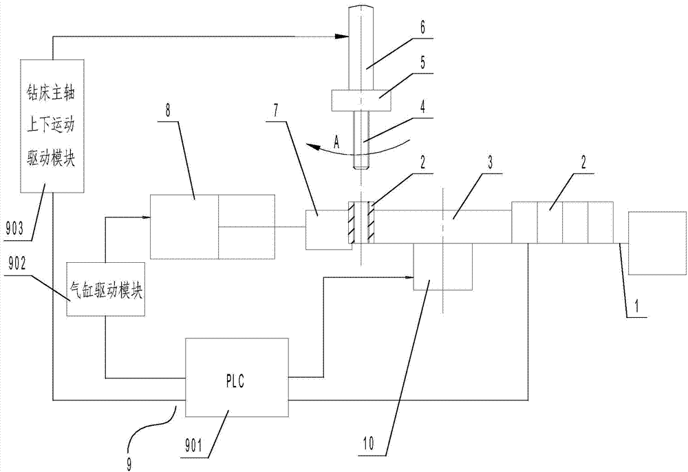
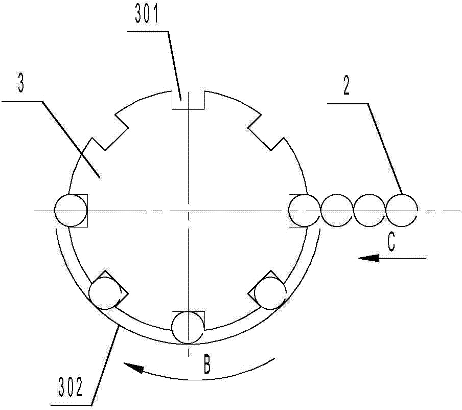
[0041] An automatic clip tapping device, including a transmission device 1, an indexing plate 3, a tap 4, a clamping block 7, and an automatic control system 9 (see figure 1 ), the tap 4 is installed on the spindle 6 of the drilling machine through the collet 5, the index plate 3 is installed under the tap 4, and is fixed on the output shaft of the stepping motor 10, and the index plate 3 is There are 8 positioning grooves 301 for placing the clip workpiece 2, one of which is located directly below the tap 4 as a processing station, and the outer semicircle of the indexing plate 3 is also provided with a stopper 302 (see figure 2 ); the conveying device 1 is located on one side of the indexing plate 3, the conveying device 1 includes a conveyor belt, a conveyor belt conveying motor, and the clamping block 7 is located on the other side of the indexing plate 3, and the clamping block 7 is connected to the clamping The output end of the cylinder 8 is connected; the drilling ma...
Embodiment 2
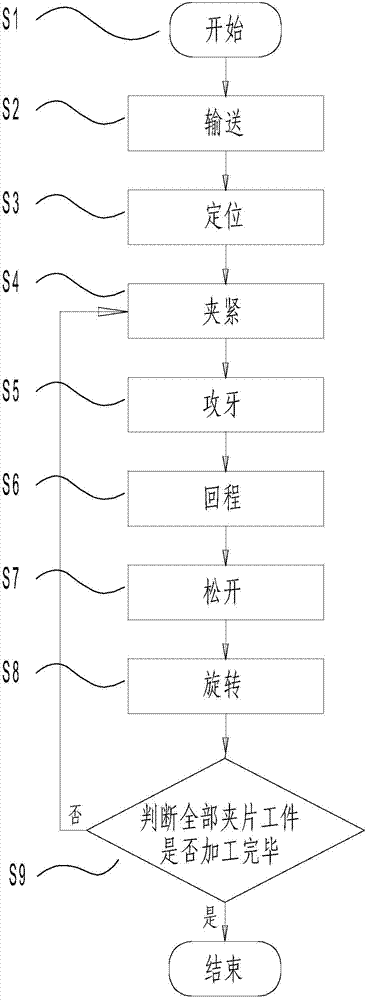
[0046] A method for automatic clip tapping, the method comprises the following steps (flow chart see image 3 ):
[0047] S1. Start: Before starting, pre-programmed in PLC901;
[0048] S2. Conveying: PLC901 sends instructions to the conveying device, and the clip workpiece 2 is conveyed by the conveying device 1 to the positioning groove 301 of the indexing plate 3;
[0049]S3. Positioning: PLC901 sends instructions to the stepper motor 10, and the stepper motor 10 drives the indexing plate 3 to rotate at a set angle and then stops, so that one of the clip workpieces 2 is in the processing station;
[0050] S4. Clamping: PLC901 sends an instruction to the cylinder drive module 902, and the cylinder drive module 902 drives the clamping cylinder 8 to drive the clamping block 7 to clamp the clip workpiece 2 at the processing station;
[0051] S5. Tapping: PLC901 sends instructions to the drive module 903 for the up and down movement of the drilling machine spindle, and the dril...
PUM
 Abstract
Description
Claims
Application Information