
Hingeless cartridge for intraocular lens injector providing haptic control

一种支撑襻、凹状部的技术,应用在喷射器领域,能够解决光学部、支撑襻损坏、难以控制光学部和支撑襻部取向等问题

Active Publication Date: 2015-07-15
BAUSCH & LOMB INC
View PDF5 Cites 1 Cited by
  • Summary
  • Abstract
  • Description
  • Claims
  • Application Information

AI Technical Summary

Problems solved by technology

For example, it can be difficult to control the orientation of the optic and haptics during movement through the cassette lumen, especially if the IOL folds or compresses inside the nozzle
Additionally, problems may be encountered during engagement of the top of the plunger with the IOL, resulting in damage to the optic, haptics, or both

Method used


Image

  • Hingeless cartridge for intraocular lens injector providing haptic control
  • Hingeless cartridge for intraocular lens injector providing haptic control
  • Hingeless cartridge for intraocular lens injector providing haptic control

Examples


Embodiment Construction

[0033] Aspects of the present invention are directed to methods of loading an IOL into a cassette that includes, by utilizing a proximal feature of the cassette, positioning the front haptics of the IOL relative to the optic of the IOL as the IOL moves into the lumen of the cassette. Fold radially inward.

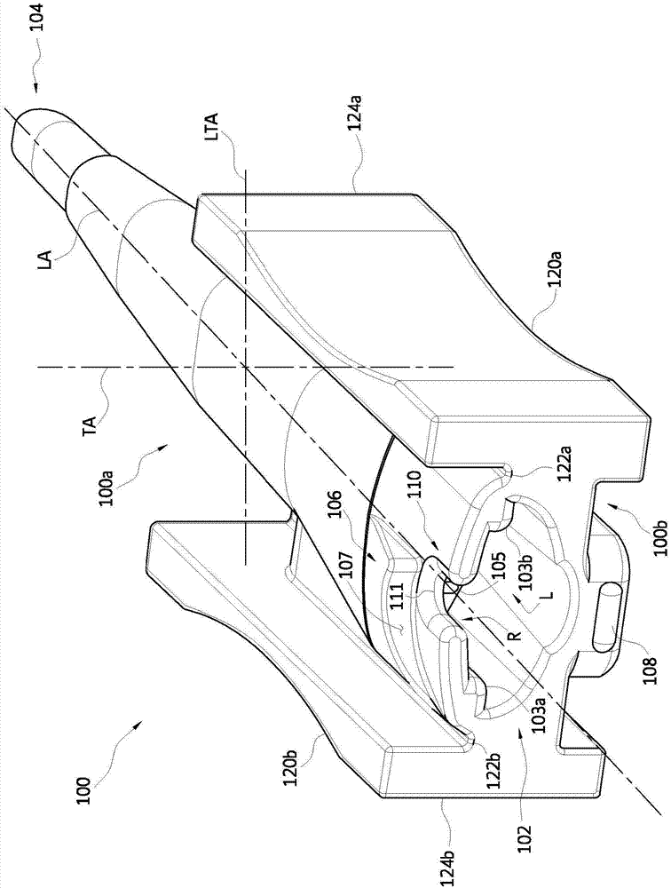
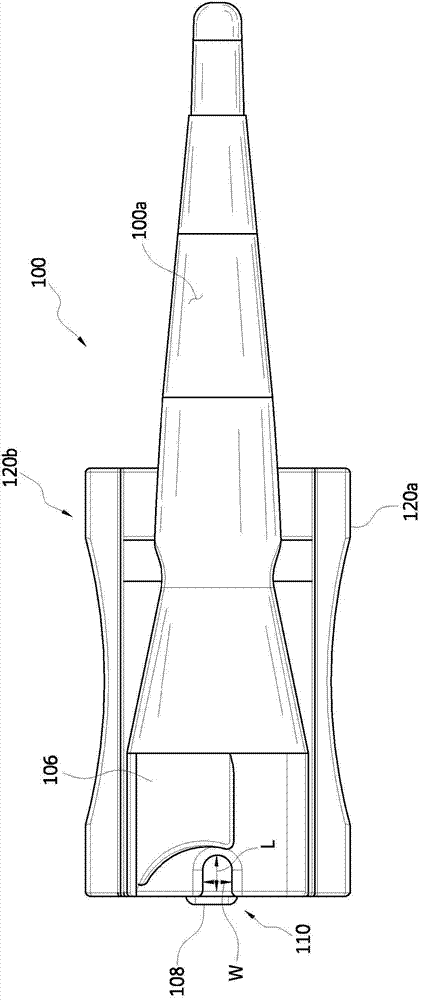
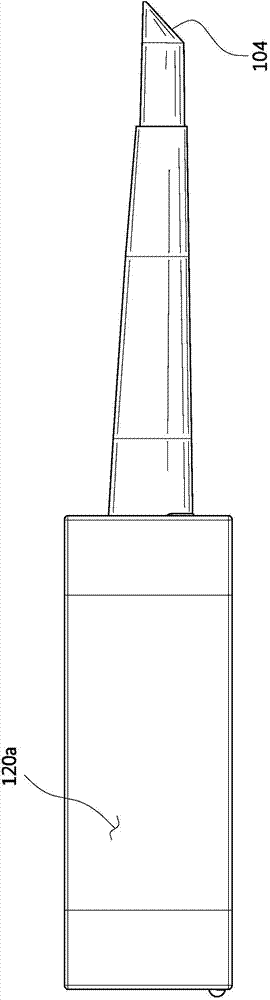
[0034] The following will refer to Figure 1-4 Embodiments of intraocular lens injector cartridges in accordance with aspects of the present invention are discussed. IOL injector cartridge 100 includes an upper wall 100a and a lower wall 100b that combine to define a lumen L . The lower and upper walls are typically integrated together, such as would be formed by a molding process; however, any suitable manufacturing technique may be used and / or multiple parts may form a cassette according to aspects of the invention. The upper wall refers to the top of the cartridge, which faces the operator when the injector is used to deliver the lens into the eye. The lumen extends f...


PUM


Abstract

A method of loading an IOL having an optic and a leading haptic into a cartridge, comprising folding the leading haptic radially inward relative to the optic as the IOL moves into a lumen of the cartridge, by using a proximal end feature of the cartridge.

Description

technical field [0001] The present invention relates to an injector for an intraocular lens (IOL) and a method of using the injector. Background technique [0002] An intraocular lens (also referred to herein as an IOL or simply a lens) is an artificial lens used to replace the natural lens of the eye when the natural lens is diseased or otherwise damaged. In some cases, the natural lens may remain in the eye with the implanted IOL. The IOL can be placed in the posterior or anterior chamber of the eye. [0003] IOLs come in a variety of configurations and materials. Various devices and methods for implanting such IOLs in the eye are known. Typically, an incision is made in the patient's cornea and an IOL is inserted into the eye through the incision. In one technique, the surgeon uses surgical forceps with opposing blades to grasp the IOL and insert it into the eye through an incision. Although this technique is still practiced today, more and more surgeons are using IO...

Claims


Application Information

Patent Timeline
Patent Type & Authority Applications(China)
IPC IPC(8): A61F2/16
CPCA61F2/167A61F2/1691A61F2/1678
Inventor M·A·瓦莱
Owner BAUSCH & LOMB INC
Features
  • Generate Ideas
  • Intellectual Property
  • Life Sciences
  • Materials
  • Tech Scout
  • Unparalleled Data Quality
  • Higher Quality Content
  • 60% Fewer Hallucinations
Learn More