Breaker with arc extinguishing device

An arc extinguishing device and circuit breaker technology, which is applied to circuit breaker parts and other directions, can solve problems such as unreasonable exhaust channel design, arc re-ignition, arc breakdown, etc.

Active Publication Date: 2015-08-12
XIAMEN HONGFA ELECTRICAL SAFETY & CONTROLS CO LTD
View PDF8 Cites 5 Cited by
  • Summary
  • Abstract
  • Description
  • Claims
  • Application Information

AI Technical Summary

Problems solved by technology

[0006] The purpose of the present invention is to provide a circuit breaker with an arc extinguishing device, which mainly solves the technical problems of unreasonable design of the exhaust passage and breakdown of the arc behind the existing products, which cause the arc to reignite.

Method used


Image

  • Breaker with arc extinguishing device
  • Breaker with arc extinguishing device
  • Breaker with arc extinguishing device

Examples


Embodiment Construction

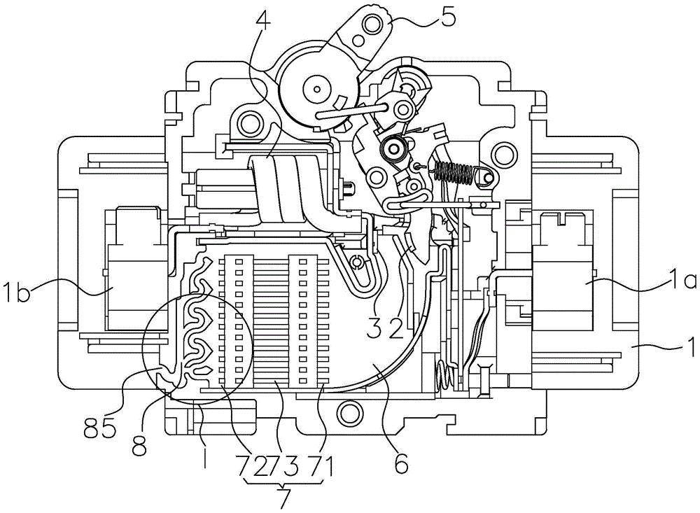
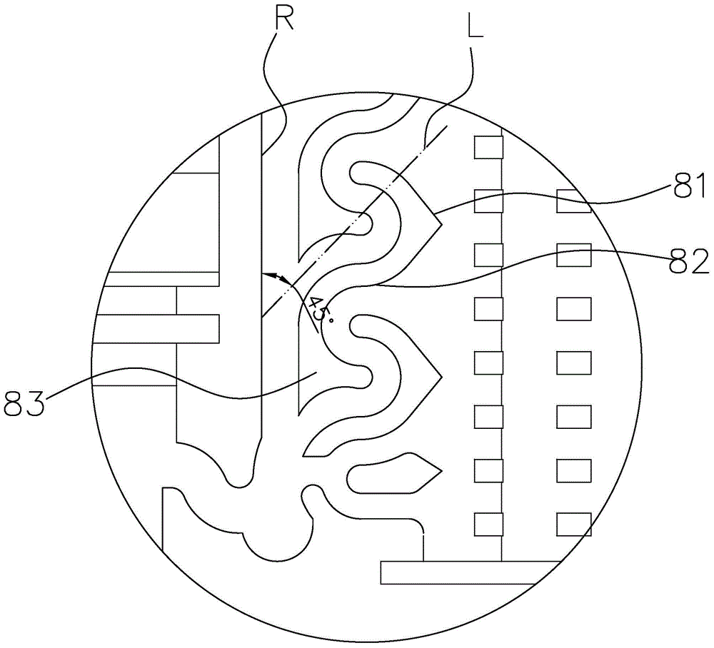
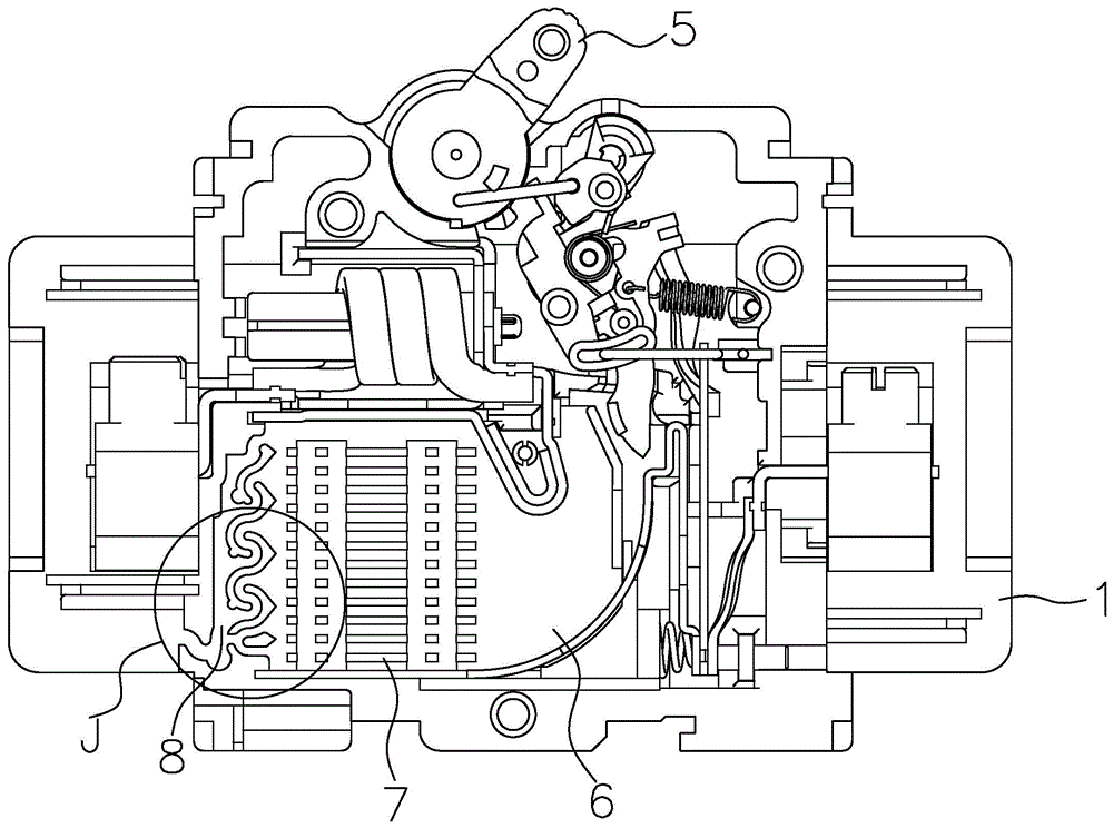
[0024] refer to figure 1 , figure 2 and Figure 5 , Embodiment 1 of the present invention discloses a circuit breaker with an arc extinguishing device, including a housing 1 and a static contact 2, a moving contact 3, an electromagnetic release 4, an arc extinguishing device and an operating mechanism 5 disposed in the housing. , as a known structure, wherein the movable contact 3 is double controlled by the operating mechanism 5 and the electromagnetic release 4. In the on state, the current passes through the terminal 1a, the static contact 2, the movable contact 3, the electromagnetic The release 4 and the terminal 1b finally form a passage to the electrical equipment. An arc extinguishing device is provided in the housing 1 located in the contact part of the static contact 2 and the moving contact 3. The arc extinguishing device includes sequentially according to the direction of gas flow. The arc starting chamber 6, arc extinguishing chamber 7 and exhaust passage 8 ar...


PUM


Abstract

The invention provides a breaker with an arc extinguishing device, so arc backside breakdown can be effectively prevented; the breaker comprises a housing and the arc extinguishing device arranged in the housing; the arc extinguishing device comprises an arc ignition chamber, an explosion chamber and an exhaust channel arranged in sequence in a gas flow direction; the explosion chamber is formed by a plurality of arc extinguishing grid sheets stacked in parallel at intervals, and comprises a gas inlet connected with the arc ignition chamber and a gas outlet connected with the exhaust channel; the exhaust channel is arranged between the explosion chamber gas outlet and a housing outer side wall and used for guiding the gas outside the housing, and provided with an anti-backflow device; the anti-backflow device comprises a shunting device and a diversion device arranged in sequence in the gas flow direction.

Description

technical field [0001] The invention relates to a circuit breaker, in particular to a circuit breaker with a built-in arc extinguishing device. Background technique [0002] refer to Figure 6 , the known circuit breaker generally includes a housing 1' and a static contact 2', a moving contact 3', an electromagnetic release 4', an arc extinguishing device 5' and an operating mechanism 6' disposed in the housing 1', Among them, the movable contact 3' is double-controlled by the operating mechanism 6' and the electromagnetic release 4'. Under the set working current condition, the operating mechanism 6' is used to connect or turn off the static contact 2' and the movable contact. The electrical connection between the contacts 3', when the operating current is greater than the set operating current such as a load short circuit, the electromagnetic release 4' overcomes the elastic force of the operating mechanism 6' and automatically disconnects the static contact 2' and the mov...

Claims


Application Information

Patent Timeline
Patent Type & Authority Applications(China)
IPC IPC(8): H01H73/18
CPCH01H73/18
Inventor 王慧德徐明
Owner XIAMEN HONGFA ELECTRICAL SAFETY & CONTROLS CO LTD
Why Eureka
Try Eureka