Booster pump and boosting method thereof

A booster pump and pressure technology, which is applied in the field of hydraulic pressure boosting, can solve problems such as application limitations, failure to meet operating needs, and plunger breakage

Active Publication Date: 2015-09-30
季金锋
View PDF9 Cites 5 Cited by
  • Summary
  • Abstract
  • Description
  • Claims
  • Application Information

AI Technical Summary

Problems solved by technology

[0003] The hydraulic pumps in the prior art are divided into gear pumps, vane pumps, screw pumps and plunger pumps according to their structures. Through the respective structural characteristics of the gear pumps, vane pumps, screw pumps and plunger pumps, the pressure ranges generated by them increase sequentially. Among them, the domestic plunger pump technology can produce high pressure between 50-80Mpa, but the high pressure of 50-80Mpa cannot meet the actual high-pressure operation needs; while the foreign plunger pump technology can reach ultra-high pressure between 100-200Mpa High pressure, such as companies in Japan and Germany, etc., but the ultra-high pressure produced by foreign plunger pump technology can only be between 0.1-0.2L / min at the same time, which also cannot meet the actual high-pressure operation needs;
[0004] Moreover, according to the unique structure of the plunger pump, the piston movement of the plunger pump is powered by the eccentric wheel, and the plunger is severely worn during long-term, high-speed reciprocating motion, and sometimes even the plunger breaks.
[0005] The supercharger in the prior art can achieve the ultra-high pressure of the ideal pressure. In this way, the ultra-high pressure is generated by the oil inside the supercharger. Since the oil circulates inside the supercharger, the supercharger can only produce intermittent Sexual high pressure value, its application is limited

Method used


Image

  • Booster pump and boosting method thereof
  • Booster pump and boosting method thereof
  • Booster pump and boosting method thereof

Examples


Embodiment 1

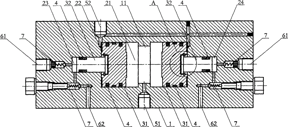
[0031] Such as figure 1 , 3 , shown in 4 and 5: a booster pump and its boosting method, comprising a booster pump main body 1, the inner middle part of the booster pump main body 1 is provided with a middle chamber, a left chamber 23 and a right chamber 24 , the middle part of the inner wall of the middle chamber is provided with a positioning column 11, and the two sides of the positioning column 11 are provided with piston rods. The positioning column 11 can position the two piston rods to prevent the end faces of the two piston rods from being separated by oil. , the piston rod is composed of an upper piston rod 31 and a lower piston rod 32, the cross-sectional area S1 of the upper piston rod 31 is at least twice the cross-sectional area S2 of the lower piston rod 32, and the upper piston rod 31 is arranged in the middle chamber, The lower piston rod 32 is disposed in the left chamber 23 and the right chamber 24 .

[0032] The middle chamber is divided into a drive chambe...

Embodiment 2

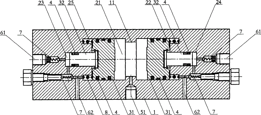
[0043] Such as figure 2 , 3, shown in 4 and 6: a booster pump and its boosting method, comprising a booster pump main body 1, the inner middle part of the booster pump main body 1 is provided with a middle chamber, a left chamber 23 and a right chamber 24 , the middle part of the inner wall of the middle chamber is provided with a positioning column 11, and the two sides of the positioning column 11 are provided with piston rods. The positioning column 11 can position the two piston rods to prevent the end faces of the two piston rods from being separated by oil. , the piston rod is composed of an upper piston rod 31 and a lower piston rod 32, the cross-sectional area S1 of the upper piston rod 31 is at least twice the cross-sectional area S2 of the lower piston rod 32, and the upper piston rod 31 is arranged in the middle chamber, The lower piston rod 32 is disposed in the left chamber 23 or the right chamber 24 .

[0044] The middle chamber is divided into a drive chamber...


PUM


Abstract

The invention relates to a booster pump and a boosting method thereof. A middle cavity, a left cavity and a right cavity are arranged in the middle of the inner side of a booster pump body. A locating column is arranged in the middle of the inner wall of the middle cavity. Piston rods are arranged on the two sides of the locating column. The piston rods comprise upper piston rods and lower piston rods. The section areas of the upper piston rods are at least two times of the section areas of the lower piston rods. The upper piston rods are arranged in the middle cavity. The lower piston rods are arranged in the left cavity and the right cavity. Through a plunger pump in the prior art, oil liquid with certain pressure intensity is provided for a driving cavity of the booster pump by a device, by controlling the ratio of the section areas of the upper piston rods and the section areas of the lower piston rods, oil liquid with certain pressure intensity is generated in the left cavity and the right cavity at the same time, namely the higher the ratio of the section areas of the upper piston rods and the section areas of the lower piston rods is, the higher the pressure intensity of the generated oil liquid is, the device generates high pressure intensity, meanwhile, large-flow oil liquid can be generated, discontinuity does not exist, and practical high-pressure working requirement is met.

Description

technical field [0001] The invention relates to the technical field of hydraulic boosting, in particular to a boosting pump and a boosting method thereof. Background technique [0002] The hydraulic pump is a component that sucks oil from the hydraulic oil tank, forms pressure oil and discharges it, and sends it to the actuator. [0003] The hydraulic pumps in the prior art are divided into gear pumps, vane pumps, screw pumps and plunger pumps according to their structures. Through the respective structural characteristics of the gear pumps, vane pumps, screw pumps and plunger pumps, the pressure ranges generated by them increase sequentially. Among them, the domestic plunger pump technology can produce high pressure between 50-80Mpa, but the high pressure of 50-80Mpa cannot meet the actual high-pressure operation needs; while the foreign plunger pump technology can reach ultra-high pressure between 100-200Mpa High pressure, such as companies in Japan and Germany, etc., but...

Claims


Application Information

Patent Timeline
IPC IPC(8): F04B9/10F04B53/14
Inventor 季金锋
Owner 季金锋
Why Eureka
Try Eureka