Machining equipment for outer surface of workpiece

A technology for processing equipment and outer surfaces, which is applied in the field of processing equipment for the outer surface of workpieces, can solve problems such as low production efficiency, and achieve the effect of improving production efficiency

Pending Publication Date: 2021-12-07
浙江博民机电股份有限公司
View PDF2 Cites 0 Cited by
  • Summary
  • Abstract
  • Description
  • Claims
  • Application Information

AI Technical Summary

Problems solved by technology

[0006] The purpose of the present invention is to address the above-mentioned problems existing in the prior art, and p

Method used


Image

  • Machining equipment for outer surface of workpiece
  • Machining equipment for outer surface of workpiece
  • Machining equipment for outer surface of workpiece

Examples


Embodiment 1

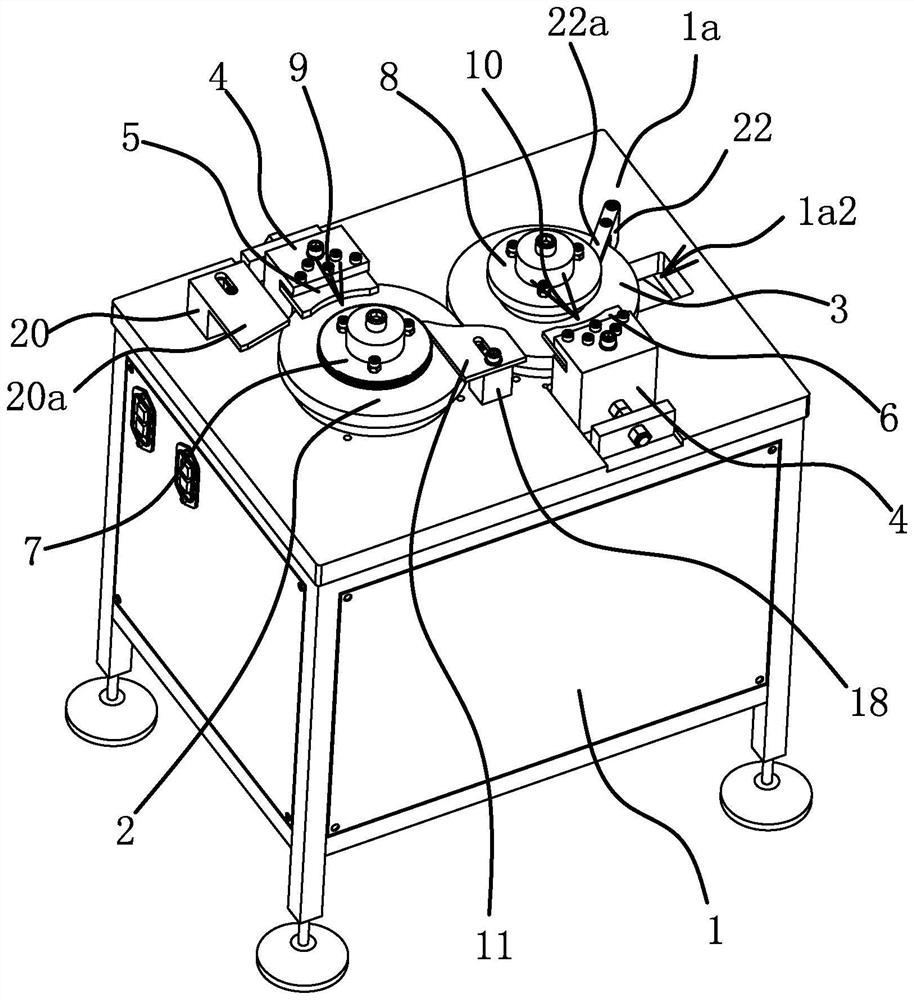
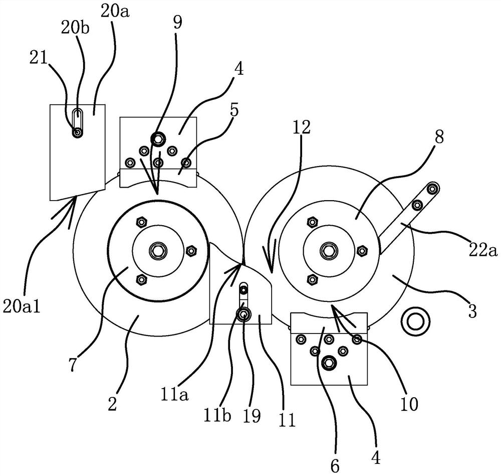
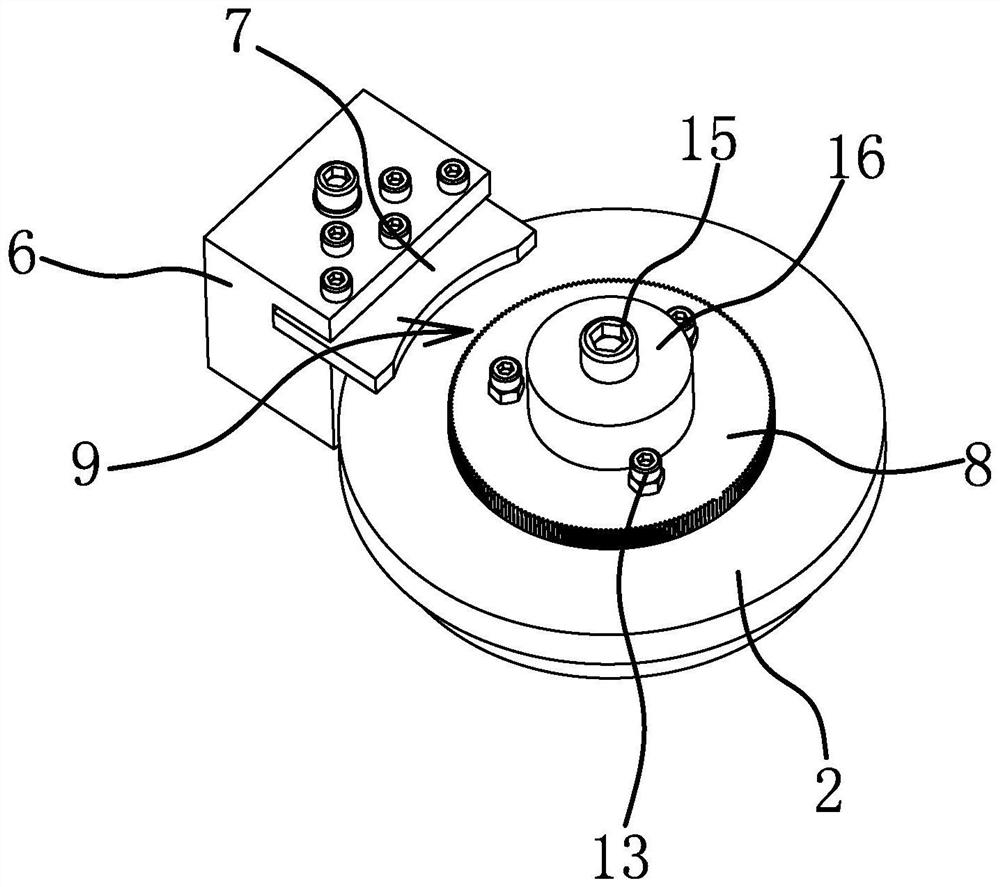
[0037] Such as figure 1 , figure 2 with Figure 4 As shown, the processing equipment for the outer surface of the workpiece includes a frame 1 with a top plate 1a and a turntable one 2 and a turntable two 3 both arranged on the top plate 1a, and the turntable one 2 and the turntable two 3 are arranged side by side. Wherein, a transmission shaft 1 23 and a transmission shaft 2 24 are rotated on the top plate 1a, the turntable 1 2 is connected to the transmission shaft 1 23, the turntable 2 3 is connected to the transmission shaft 2 24, and two motors 25 are connected below the top plate 1a. The output shaft of one of the motors 25 is connected with the lower end of the transmission shaft one 23 through a coupling 26 , and the output shaft of the other motor 25 is connected with the lower end of the transmission shaft two 24 through a coupling 26 . On the top plate 1a, mounting seats 4 are respectively fixed on the sides of the turntable 1 2 and the turntable 2 3, and the mou...

Embodiment 2

[0045] The structure and principle of the present embodiment are basically the same as those of the first embodiment, the difference is that in the present embodiment, the arc surface one and the arc surface two are smooth surfaces, and the outer peripheral surface of the disc one 7 and the disc two 8 The outer peripheral surface is provided with continuously distributed teeth, that is, the hobbing of the lower outer surface of the workpiece is completed in the first forming channel 9 and the gear hobbing of the upper outer surface of the workpiece is completed in the second forming channel 10 .

Embodiment 3

[0047]The structure and principle of this embodiment are basically the same as that of Embodiment 1. The difference is that in this embodiment, the outer peripheral surface of disk 17 is a smooth surface, and the arc surface 1 is protrudingly provided with fonts, and the arc surface 2 It is a smooth surface, and the outer peripheral surface of the disc two 8 is provided with continuously distributed teeth, that is, the workpiece completes the hobbing process on the lower outer surface in the forming channel one 9 and completes the hobbing process on the upper end outer surface in the forming channel two 10 .


PUM


Abstract

The invention provides machining equipment for the outer surface of a workpiece, and belongs to the technical field of machining. The machining equipment solves the problem that the production efficiency is low. The machining equipment comprises a top plate, a first rotating disc, a second rotating disc, a first matching plate and a second matching plate, wherein the first rotating disc, the second rotating disc, the first matching plate and the second matching plate are arranged on the top plate. A first disc is arranged on the first rotating disc, and a first forming channel which can conduct gear hobbing or character hobbing on the workpiece when the first rotating disc rotates is formed between the end of the first matching plate and the peripheral face of the first disc. A second disc is arranged on the second rotating disc, and a second forming channel which can conduct gear hobbing or character hobbing on the workpiece when the second rotating disc rotates is formed between the end of the second matching plate and the peripheral face of the second disc. The first rotating disc and the second rotating disc are arranged side by side and are opposite in rotating direction, and the first forming channel and the second forming channel are different in height. A material guiding plate is further arranged on the top plate in parallel. An inclined material guiding face is arranged at the end of the material guiding plate, one end of the material guiding face is located on the first rotating disc and is close to the projection of the first disc on the first rotating disc, and the other end of the material guiding face is located on the second rotating disc. The machining equipment has the advantages of being high in production efficiency, high in automation degree and the like.

Description

technical field [0001] The invention belongs to the technical field of processing and relates to processing equipment for the outer surface of workpieces. Background technique [0002] In the current field of mechanical processing, in addition to using CNC machine tools for conventional machining, other processing equipment will be used to process parts. Taking cylindrical workpieces as an example, gear hobbing machines will be used to hob the outer surface of the workpiece. Or use a letter rolling machine to roll letters on the outer surface of the workpiece. [0003] For example, a knurling machine disclosed in the patent application number 201621282337.7 includes knurling teeth and a turntable assembly. There are at least two, the axes of all the rotation axes are on the same circumferential line of the turntable, the shaft ends of the rotation axes protrude from the surface of the turntable to fit the workpiece to be knurled, and the inner surface of the knurled teeth i...

Claims


Application Information

Patent Timeline
IPC IPC(8): B44B5/00B44B5/02B23P9/02
CPCB44B5/00B44B5/024B44B5/026B44B5/02B23P9/02B44B2700/12
Inventor 郑志勇牟方奎周兴良魏鑫董雷涛张伟
Owner 浙江博民机电股份有限公司
Why Eureka
Try Eureka