Method of determining boundary of drag acceleration corridor of glide vehicle

A technology of acceleration and aircraft, applied in the field of data processing, can solve the problem that the drag acceleration corridor cannot be expressed analytically

Inactive Publication Date: 2015-11-04
BEIJING AEROSPACE AUTOMATIC CONTROL RES INST
View PDF3 Cites 5 Cited by
  • Summary
  • Abstract
  • Description
  • Claims
  • Application Information

AI Technical Summary

Problems solved by technology

However, since the drag acceleration corridor cannot be expressed analytically, it can only be calculated point by point by numerical calculation
There is a lack of good methods in the prior art to approximate the drag-acceleration corridor as a function of energy

Method used


Image

  • Method of determining boundary of drag acceleration corridor of glide vehicle
  • Method of determining boundary of drag acceleration corridor of glide vehicle
  • Method of determining boundary of drag acceleration corridor of glide vehicle

Examples


Embodiment Construction

[0056] In order to make the technical problems, technical solutions and advantages to be solved by the present invention clearer, the following will describe in detail with reference to the accompanying drawings and specific examples.

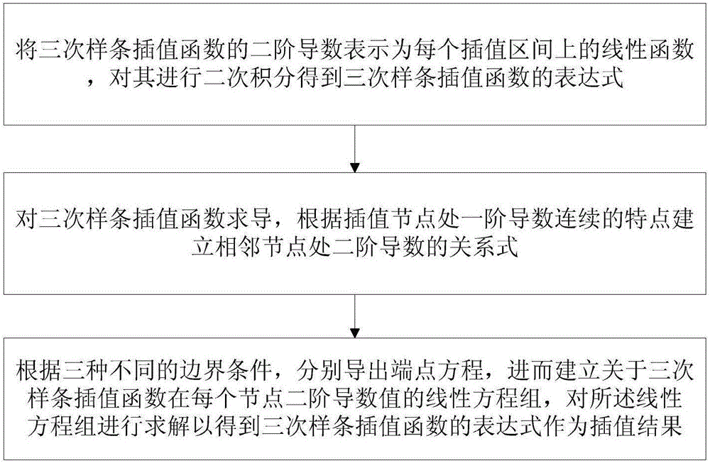
[0057] The flow process of the embodiment of the present invention is as figure 1 shown, including:

[0058] Express the second-order derivative S″ (x) of the cubic spline interpolation function S (x) as a linear function on each interpolation interval, carry out quadratic integration to it and obtain the expression of the cubic spline interpolation function S (x);

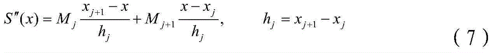
[0059] Deriving the cubic spline interpolation function S(x), according to the continuous characteristics of the first-order derivative at the interpolation node, the relational expression of the second-order derivative at the adjacent node is established;

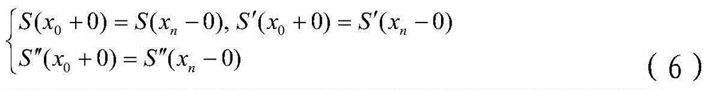
[0060] According to three different boundary conditions, the endpoint equations are derived respectively, and then the secon...


PUM


Abstract

The invention discloses a method of determining a boundary of a drag acceleration corridor of a glide vehicle. The method comprises the following steps: expressing a second derivative S'' (x) of a cubic spline interpolation function S (x) as a linear function on each interpolation interval, and performing quadratic integral on the second derivative S'' (x) to obtain an expression of the cubic spline interpolation function S (x); taking the derivative of the cubic spline interpolation function S (x), and establishing a relation of a second derivative at the adjacent nodes according to the characteristic that a first derivative is continuous at an interpolation node; respectively deriving endpoint equations according to three different boundary conditions, so as to establish a system of linear equations for the cubic spline interpolation function S (x) at each node second derivative value Mj (j=0,1, to n), solving the system of linear equations to obtain the expression of the cubic spline interpolation function S (x) as the interpolation result.

Description

technical field [0001] The invention relates to the technical field of data processing, in particular to a method for determining the boundary of a drag acceleration corridor of a gliding aircraft. Background technique [0002] The re-entry corridor of the gliding flight of a hypersonic vehicle refers to the area determined by two Kepler orbits at different altitudes that the spacecraft returning to the earth must pass through when re-entering the atmosphere. For re-entry corridors with unlimited landing zones, the velocity of the spacecraft when it enters the atmosphere can be converted into the perigee altitude of the Kepler orbit. A Kepler orbit with a higher perigee is the upper boundary of the re-entry corridor, a Kepler orbit with a lower perigee is the lower boundary of the re-entry corridor, and the difference between the heights of the two perigees is the width of the re-entry corridor. [0003] In the prior art, the reentry corridor of the gliding flight of a hype...

Claims


Application Information

Patent Timeline
Patent Type & Authority Applications(China)
IPC IPC(8): G06F17/50
Inventor 杨业马卫华包为民黄万伟祁振强禹春梅唐海红吴浩
Owner BEIJING AEROSPACE AUTOMATIC CONTROL RES INST
Why Eureka
Try Eureka